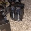
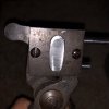
HP inset bar

Brad

Benevolent Overlord and site owner
Staff member
Pretty impressive if you wined up with something usable for a first try with this type of project, especially at the hobby level. Nice work, Brad.

I reckon a second retrofit might go easier/faster. Anything you would do different if you tried another?
I would do like Keith did and make a rectangular bar that went the width of the mould. That makes the killing of the mould faster, making the bar faster, and the cross pins enter at a right angle to the bar.

This was a good learning experience. I did learn a bunch.
 

Brad

Benevolent Overlord and site owner
Staff member
Ready for a test run.
Those HP are gonna be huge!

Learned a big lesson. While precision is nice you need tolerances of something is supposed to move within another piece. The slide pins are .002 undersized and are about perfect. My HP pins were binding the mould and I had to increase the hole size in the mould to .004 oversized.
 

Attachments

  • FC59326E-C2BC-4747-9E20-DA0E2BC82BD7.jpeg
    FC59326E-C2BC-4747-9E20-DA0E2BC82BD7.jpeg
    102.4 KB · Views: 0
  • BF2744B2-5C4E-4CE5-9106-3F46ED02760E.jpeg
    BF2744B2-5C4E-4CE5-9106-3F46ED02760E.jpeg
    53.1 KB · Views: 0

Rick

Moderator
Staff member
They look awfully big to me, a really soft alloy at very low velocity or simply blow the nose off IMHO.
 

Brad

Benevolent Overlord and site owner
Staff member
These will never be used for hunting, that is for sure. This was purely a proof of concept build.
I will be interested to see how they behave when fired into the berm. Yet will need to wait for things to thaw.
 

Ian

Notorious member
Brad, a trick to check fit is soot. Get a paint stir stick or similar, dip about an inch of the tip in mineral spirits or kerosene if you have any, light it on fire and smoke the entire inside of the mould halves. Insert your inset bar and put the mould halves together. File the shiny spots. Repeat.

This is how to sink a tang into a buttstock with the "it grew there" fit, and it works for many things.
 

Ian

Notorious member
Forgot to add....about tolerances, they have to be there and it is surprising how much is required. The first ejector pin I made for the two-diameter bullet sizing dies I made with .005" clearance and could barely get the pin in there with both thumbs. Ended up polishing to .001" total clearance and it freed up. Then I oiled it and it was back to a press-fit. .002" turned out to be just enough with 7wt. ATF as a lubricant.

Moulds have the additional challenge of having to function when hot. Steel expands at a rate of about .001" per inch of diameter per 100 degrees F, and depending on the relative shapes, tolerances may become larger....or smaller. I can't tell you how fit of the pins and inset bar will change within the blocks as the assembly reaches casting temperature, but expect to have to re-fit things after your first attempt casting with it.
 
Last edited:
F

freebullet

Guest
With it in the block & open there, I can tell that would be a nightmare to machine that radius with all the hardware coming together. Rectangular block would make it easier in such a small block size.

You could machine a flat meplat edge & re-taper the pin for a less aggressive point. For that matter, you could convert it to a rectangular block, shouldn't be to hard having locating holes in the mold block already. I dunno
 

fiver

Well-Known Member
i think you figured out what I was saying.

oh one more thing, as the parts heat up and get a blue on them they will add some more diameter.
probably close to .001.
 
Last edited:

Brad

Benevolent Overlord and site owner
Staff member
Good news and bad news.

Bad news is that I made the pins too big and the nose is very thin. It also tends to give some flashing on one side of each cavity forward of the nose.

Good news is that it works like it should. A little lube on the pins and they slide like they should. Bullets drop right off the pins.

No desire to do this to another mould. This was a mould I did some other experimental work on. Chose it because it cast right at .429 and that lead to me really understanding what leading is. I had lathe bored the bands a bit larger but still never use the mould. I have a nice NOE 503 that gets used.
 

fiver

Well-Known Member
you basically need a squared off step on the end of the pin.
basically a distinct cylinder with a cone set on top of it.
I think this was a good learning project.
 

Brad

Benevolent Overlord and site owner
Staff member
I am thinking that the MP style might be easier to do. Drill for the pin, get the pin made, then drill for the lose pins and tap them into the HP pin. No bar to make, no pocket to machine.
 

fiver

Well-Known Member
I think each type has their advantages.
your also allowed to have some slop everywhere but where the lead meets the steel so to speak.
I can see the advantage of easily replaceable pins though.
 

Ian

Notorious member
Good angle on the points. My Lyman Devastator .45 comes to a razor edge at the hp mouth and expands beautifully at 900 fps.
 

KeithB

Resident Half Fast Machinist
I would like to make a few points without criticising anyone else's processes.

1. When I made a similar mold I threaded the pins so I could move them up or down as needed to accommodate different pin sizes/styles and provide for a little larger manufacturing tolerance window for the pins themselves.

2. The pin style MP uses is simple and seems to work well for people but again putting a tapped hole in the pin fixes the location of the HP pin within the mold and brings us back to point 1.

3. Drilling from one direction to make the HP hole and then turning the mold 90* to make the cross holes can create tolerance/location issues. I thought that drilling the cross holes in the mold half with the inset bar in place removes any accuracy issues, and drilling the HP holes in the mold and bar with the bar pinned in place in the mold does the same. The cross holes and HP pin holes do not have to be directly in line this way. If you use the HP holes to be threaded and intersect the cross pins to lock them in place there is a much larger tolerance range in that overlap.

4. For any mold over two cavities drilling two cross holes and X number of HP holes is less overall work, takes less material out of the mold, and greatly reduces the accuracy/tolerance/clearance issues involved.

There are lots of ways to skin a cat and HP a mold, I just thought I would share my thinking processes. I almost always go for simple and try to do things that gives me the broadest tolerance range and the fewest steps.
 

fiver

Well-Known Member
I think MP has an advantage the home guy's don't.
his CNC cuts the cavity and the through hole all in one shot.
he is already indexed for the next step and it is just another tool aimed at the block.
everything done on an older mold at home has to have a reference point established and the center point is likely skewed from hole 1 to hole 2 just from general wear and tear.
 

Brad

Benevolent Overlord and site owner
Staff member
If I did it again I would thread the HP pins for exactly the reason Keith started.
Drilling for HPand cross pins was done with the bar in place, it reduces the error potential. For the cross pins I drilled with tap size bit, removed the bar, then drilled the clearance holes for the pin diameter.

Order of operation is critical.