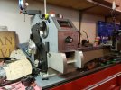
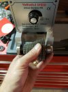
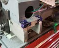
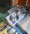
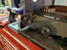
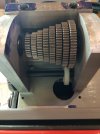
New lathe "kit" fresh from Shanghai

Ian

Notorious member
I wanted a little bit bigger lathe and have plans to do something a little different with my old faithful Grizzly 7x14, so I bought one of the cheeeeeeaaaap Chinese benchtop lathes from a fleabay vendor. They'd gotten down to around $1200 shipped for an 8.7x29.5", 1.5 HP model having a 38mm spindle bore and belt drive. Problems are many, among them being they are all metric and have very limited threading capability (2.0mm per turn leadscrew, no thread dial, and an oddball 56-tooth spindle gear driving the change gears). I figured I'd have to do some milling and scraping and a lot of disassembly and cleanup with precision stones no matter what brand I bought so might as well get the cheapest one I could new and not have to deal with worn out and half-broken old South Bend or Atlas hobby machines and their limitations (mainly tiny spindle bore). The other option is buy a PM 11-30V for $4,000 delivered and then have to buy a bunch of new tooling for the bigger tailstock, tune up the whole thing, and be not all that much further ahead than what I ended up doing for about $2,500 less.

Well, I learned a lot. First off, the super-cheap no-name Chinese lathes are made from reject and scrap parts that didn't make the quality cut for the big name importers. Second, I decided to turn this into a REAL project which involves what I'm about to outline.
Step the first was check the bed for flat and straight to see if I had something to work with before choosing my option to send it back. It looked good so I tore it all apart and went to cleaning and fixing stuff like the bottom lips of the ways which were machined so poorly that it was impossible to adjust the carriage to be snug to the bed. I cleaned about a double handful of petrobond, paint, and flashing out of the innards of the bed, cleaned up the body work, primed, and repainted the whole bed. Then I set it up in my milling machine and trued up the underside of both ways. After that I scraped those surfaces in by hand to get less than .0003" total thickness variation for the entire length of 30". This took three setups per side and about 8 hours of tramming.
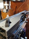
20220624_172951.jpg

After that, I checked the saddle for being level to the bed and of course it wasn't, so I re-cut the vee-way guide and trued all the major surfaces to the cross-slide ways in one setup on my South Bend 7" shaper.
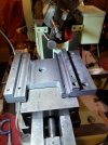
20220628_214843.jpg

Next I scraped in the the saddle, shaped off the top of the apron to line up with the leadscrew again, and put the headstock back on to check its alignment. I was getting just about perfect vertical alignment and about a thousandth twist over 8" by making two small, very light cuts on an unsupported aluminum rod. Good enough.
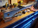
20220629_195817.jpg

Next was to figure out how to make this thing cut imperial threads with zero error. This turned into a rabbit hole of epic proportions because of the 56-tooth spindle gear and lack of a reverse feature for the leadscrew. Building a quick-change gearbox, a reversing tumbler, and a new banjo system to provide both reverse and arithmetically correct leadscrew drive for imperial threads as well as something smaller than a .0065" minimum feed rate for decent finishes is the only practical way to pull this off. Changing the leadscrew to imperial threads and re-threading the half nuts is also required.

Then I decided to pull apart the spindle and replace the sealed bearings with tapered roller bearings. To my surprise, this thing had a sealed bearing on the outboard side and a single, tapered roller bearing on the inboard side behind the chuck, WTF???? Grease sucks so I'm also going to install real seals instead of sheet metal shields for the bearings and run them in light oil. I polished the inboard spindle journal to be a 57mm sealing surface (it takes a lathe to make a lathe!)
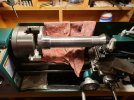
20220707_212858.jpg

After spending quite a few evenings figuring out gear tooth count, ratios, feeds, and what gears were available, I bought two sets of metal change gears and started work. I got the tumbler and banjo spacing, gearing, and arithmetic sorted out (I think) and a 16 TPI RH 36" leadscrew and 12mm keyed shaft sourced from McMaster-Carr. Bearings and bushings courtesy of Jeff's Dollarama.
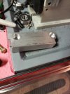
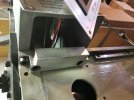
20220709_183229.jpg
20220709_190106.jpg

20220709_221119.jpg

20220709_221029.jpg

The list:

  1. Make a quick change gearbox housing, bore for bearings, install gears and shafts. Done 7/23
  2. Make quick-change sliding lever and install bushings, sliding gear, idler gear, and shaft.
  3. Make seal plates for both ends of the headstock, source seals, and install spindle with new tapered roller bearings. Done 7/24
  4. Bore and cut keyway in a 60-tooth gear for the spindle. Done 7/24
  5. Make spindle gear spacers Done 7/24 and re-locate spindle speed sensor and magnets.
  6. Make and install stud gear stud on left side of headstock.
  7. Make tumbler, lever, and detents, tumbler gear studs, and install tumbler assembly.
  8. Make stud gear shaft.
  9. Make banjo stud/bearing housing. Done 7/21
  10. Make banjo.
  11. Turn, key, and thread ends of new 3/4x16 Acme leadscrew. DONE 7-16-22
  12. Fixture, bore, and thread half nuts to 3/4x16 Acme. DONE 7-16-22
  13. Install all parts and make inboard leadscrew drive gear cover.
  14. Rebuild the belt drive system and maybe install a third belt and reduction pulley.
  15. Fix or replace the tailstock, it's pathetic, no way to make anything precise with it. Maybe convert it to imperial and replace dial.
  16. Make new leadscrew and dial for the cross slide.
  17. Make metric conversion dial for the compound slide.
  18. Replace the lantern post with an Aloris-style QCTP.
  19. Buy and fit a 4-jaw chuck.
  20. Make an outboard spider.
  21. Put roller bearing tips on the steady and compound rests.
  22. Make an MT5x5C collet holder and drawbar system.
  23. Make an 8" face plate.
  24. Make STUFF!
 
Last edited:

JustJim

Well-Known Member
Last week, I briefly considered purchasing an import lathe as a learning tool, before rejecting the idea. Seeing what you're going through here to get this one up and running confirms that for once I made a good call!
 

Brad

Benevolent Overlord and site owner
Staff member
Mine runs pretty damned well but I paid for a different level of quality.

China is very good at making a product to the price point asked for. Quality is possible, for a price.

Ian, that is gonna be one hell of a project.
 

Ian

Notorious member
I've been very pleased with my 7x14 Grizzly, it's a much better machine made from the same castings as the no-name products. I've had to fix a few things including re-milling the tailstock base on square with the bed to get rid of the misalignment issue as the tailstock quill was advanced, and also ended up hand-scraping the way guides on the saddle to get rid of a slight but annoying rock which made finish cuts ugly. I upgraded to a 5" chuck from LMS, stoned and adjusted gibs, and some other tune-up items and will soon be replacing the spindle gears and converting to tapered roller bearings as the sealed bearings have finally given up after several years of punching way over their weight class and doing lots and lots of case prep operations. I've re-barreled three rifles and threaded many muzzles with this little machine quite accurately, cut bullet moulds on it, made all sorts of reloading tools, fixed car parts, you name it. It was well worth the $715 it cost before the big import taxes bumped all this stuff up 25%. Still worth it IMO but spend the money for a BETTER Chinese benchtop lathe if you don't have a lathe, mill, tools, and skills already to do serious precision machine reworking.
 

Ian

Notorious member
Mine runs pretty damned well but I paid for a different level of quality.

China is very good at making a product to the price point asked for. Quality is possible, for a price.

Ian, that is gonna be one hell of a project.

Remember, I like most Lee Precision tools. Having retired from automotive service and making space in the shop for another 8' rolling tool cabinet, and loaded tool cart, and also an extra gun safe, I don't have room for a big unit like yours. I shopped and shopped old 'Murican iron in the 2k-5K range and I just can't get a truck that can handle a 2500lb machine down my driveway, nor can I afford the machine, freight, AND the expense of freighting the saddled-out bed to Illinois or somewhere to be re-ground as well as converting from 3-phase or buying and installing a 5HP rotary phase converter. What I'm doing is a better option than the old garage models since none of them had a decently sized spindle bore. The PM 11-30V is probably the best turnkey option for what I needed, but they're backordered as usual and I can buy a lot of rifle barrels and action steel bar for the extra $2500+ accessories that would cost me. I figure I can sink another $600-700 into this benchtop unit and have fun enginerding it out the way I really want and have enough machine to do most of what I realistically need.
 

Brad

Benevolent Overlord and site owner
Staff member
You also have an innate need to tinker. It is in your DNA and is a huge part of what makes you you.

I applaud the effort, I am a bit in awe really.

Maybe Walter could stop by and make a video of the work
 

Dimner

Named Man
You also have an innate need to tinker. It is in your DNA and is a huge part of what makes you you.

I applaud the effort, I am a bit in awe really.

Maybe Walter could stop by and make a video of the work
You nailed it. Sometimes a man just needs a Quest. Saving 1k might not be the most fun when all there is to do is just use the machine as intended.

When I did my ar15 cast bullet project (had a bunch of special requirements that made it more labor intensive than usual) a friend asked me "why spend so much time trying to all that to work when, even now, 22 call bullets are 13cents each?". My response was that I was still kinda bummed the project was over and successful.
 

Dimner

Named Man
Ian, I'm wondering....

What would this lathe be good for under its original condition. I don't speak "lathe", but if I'm understanding your post, the product as is had serious issues even if someone were to leave it metric. Who's the intended consumer for this product, or is it just to get rid of cast off parts?

Also, love to see the writeup and photos. Lathework, millwork, machining has always been fascinating to me.
 

Bret4207

At the casting bench in the sky. RIP Bret.
You also have an innate need to tinker. It is in your DNA and is a huge part of what makes you you.

I applaud the effort, I am a bit in awe really.

Maybe Walter could stop by and make a video of the work
BINGO! You hit the nail on the head- he's a born tinkerer! And yeah, X2 on the applause!
 

Bret4207

At the casting bench in the sky. RIP Bret.
Great job Ian. If it floats yer boat, go for it. Those tiny headstock holes in the smaller US lathes are a problem for sure. I'm impressed man!
 

smokeywolf

Well-Known Member
Another thing that Ian deserves accolades for is his very well framed and detailed pictures. I think even JW would approve.
 

Ian

Notorious member
A little more progress. Got the front mounting cross bar installed and secured to the headstock. Might do some decorative edge milling later or maybe just round off the corners. Still have to source a plate for the front.

20220710_201017.jpg

Time to locate and drill the shaft holes and bore the bearing holes in the sides of the gearbox. Two shafts will go through spaced by the mesh of two 60-tooth gears. One shaft is concentric with the leadscrew and is located on the left side plate based on the center of the leadscrew after I adjusted the original leadscrew mount to the saddle and took detailed measuremements off of reference surfaces. Here the first hole is drilled through at 1/2", will bore it to depth for a bearing and center the gear with a 12mm rod through the bearing in the same setup. Then position the driven gear in proper mesh, center punch, and drill the other shaft hole through both sides at 1/2", bore that one's bearing pocket, then take the side plates out of the vise and indicate and bore the bearing pockets on the other side. Best way I could figure to do it, anyway.

20220710_210337.jpg
 

Snakeoil

Well-Known Member
Truly a labor of love. I'm impressed with your commitment to detail and a accuracy.

I took a close look at my South Bend 10H a couple years ago and thought about rebuilding it. It still has a War Dept acceptance plate on the base from WWII. Then I realized that I'd probably need it for something and not have it available. Decided I can live with it as-is. When I can't shoot or ride bikes anymore, maybe I'll revisit the lathe. Or if it starts cutting ovals, I might take a closer look.

I do wish it would cut metric threads. Looked into the gear set and kinda gave up.
 

Ian

Notorious member
Should be able to cut metric threads with a transposition change gear if the heavy 10 has a banjo that feeds quick-change box. A 47/37 compound gear will get you 0.02% error, a single 127-tooth gear will get no error but there would be some fabrication involved to make room for it. Basically you combine the metric 1.27:1 ratio of the change gears with the basic divisions of the letter quick change box and some of the number gears to get your metric ratios with an imperial leadscrew. An example would be put the same gear on your qcgb input as the stud or spindle gear and the transposition gear in-between, put your letter box in "direct" (no reduction), and set your number qcgb to 50 teeth for a 16 TPI leadscrew and it will cut 1.0mm per turn. Set the letter box for 2:1 and you get .5mm per turn. Direct on the letter box and 40 teeth on the number box results in 1.25mm feed per spindle rotation, etc. Different figures for a 10-pitch leadscrew or whatever your lathe has, but basically that's it.

I sort of copied a design someone else worked out for a machine similar to the SB model 9C that didn't come with a qcgb. It has a reversing tumbler driven by the spindle and a stud gear shaft that permanently turns at spindle speed but has a changeable stud gear and changeable input gear for the homemade qcgb. There is one compound gear on a banjo that connects the two. The stud gear and qcgb input can have 20, 40, or 80 teeth and an 80/40, 80/20, and either 47/37 or (in my case) 63/52 metric transposition gear are fitted in-between to keep changes simple. The 80/40 is used for all imperial threading ratios, the 63/52 for all metric, and the 80/20 is for all turning feeds. The stud and qcgb inputs are changed for some threading ratios and 20 stud/80 qcgb input are left in place for all turning feeds. The qcgb has 40-tooth idlers which can be coupled with a 30, 35, 40, 45, 50, 55, 60, or 65 tooth gear to get the needed output ratios to yield 6 tpi through about .002" feed rates and a good bit of the metric ones. There will of course be a few gaps but that can be addressed as needed with special sized gears on the stud and qcgb input as required. Due to self-imposed space constraints my particular configuration requires a pair of 60-tooth gears to bring the qcgb output back to the leadscrew (small SB and Logan boxes actually do the same thing because the largest change gear won't tuck against the bed under the spindle close enough to line up axially with the leadscrew, same problem I have). Since I didn't want to stack all the qcgb gears out on the outboard end of the headstock where it would line up with the leadscrew directly, the two extra gears (pictured above last photo, but will actually be installed on the other side of the qcgb) were necessary and the leadscrew will require righthand threads in the single-tumbler-gear position (preferred for normal leadscrew direction). Reverse uses two tumbler gears and is more wear and slop but allows left hand threading and left-to-right feed direction.
 
Last edited:

Ian

Notorious member
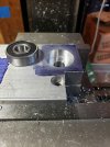
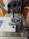
Boring is so named for a reason. "Tediousing" might be a better term. First hole:

20220711_202537.jpg

Ta-DAA! This one will get the banjo stud/bearing flange put over it to secure the bearing. I forgot to relieve the bottom of the pocket for a snap ring that retains the shaft but did that later.

20220711_203831.jpg

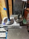
Setting up and marking the hole spacing. Advanced involute gear math AKA a strip of paper ensures proper tooth clearance.

20220711_205308.jpg

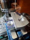
Drilled hole and bored the second pocket in one setup. Couldn't drill through at the time due to location on milling vise, pass-through hole for shaft is non-critical so I'll drill it through later.

20220711_215807.jpg

Two down, two to go, time for bed.
 
Last edited:

Bret4207

At the casting bench in the sky. RIP Bret.
Truly a labor of love. I'm impressed with your commitment to detail and a accuracy.

I took a close look at my South Bend 10H a couple years ago and thought about rebuilding it. It still has a War Dept acceptance plate on the base from WWII. Then I realized that I'd probably need it for something and not have it available. Decided I can live with it as-is. When I can't shoot or ride bikes anymore, maybe I'll revisit the lathe. Or if it starts cutting ovals, I might take a closer look.

I do wish it would cut metric threads. Looked into the gear set and kinda gave up.
Judging by what I read and watch the SB change to metric isn't that hard. I'm pretty sure the component (change gears) are available on Ebay.
 

Charles Graff

Moderator Emeritus
That is quite a project that requires much skill and knowledge. It makes my head hurt just thinking about it. Best of luck and keep us posted.
 

Snakeoil

Well-Known Member
Should be able to cut metric threads with a transposition change gear if the heavy 10 has a banjo that feeds quick-change box.
Thanks for taking the time to type that out. I guess I'll have to revisit the subject when Fall arrives. I have a box of gears for an old Atlas in my barn at the lake. I think I'll go see what is in there. Might have what I need and just need to machine some adapters to use them.

I saved your write-up to my South Bend folder and when I did, I noticed I'd saved other info on cutting metric gears. In that file was a chart with photos showing the same set-up that you described using the same gear tooth counts.

UPDATE: Rather than start another thread, I thought I'd add what I found today. First, I found a guy that figured out that just changing the stud gear can give you metric threads. He has a spreadsheet I downloaded that lets me calc the gears I need. Saved me having to do the arithmetic. Then I took a look on ebay and found other 10H transposition gears with a different ratio that looks like it might fit without alternations or mods being required. 3D printed gears so cheap at $54. But this winter, making the gears just might be a good winter therapy project. Glad you gave me the incentive to revisit this subject.
 
Last edited:

Ian

Notorious member
20220712_213737.jpg

Bearing bores all done and bearings pressed in. Gear mesh came out right on but can't mount the driven gear for the leadscrew with the QCGB mounted until I clearance the lathe bed a little.

Here you can see the change gear setup and the drive gear that eventually will be captured in the sliding lever.

20220712_213444.jpg