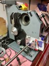
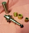
New lathe "kit" fresh from Shanghai

Ian

Notorious member
I've taken to filling a pump spray bottle with Kool-Mist mix for certain operations on the lathe. I have a mister on the milling machine but need to make a mount that's better than a magnet taped to the back of the mister valve/base. For a hobby machine shop and small machines lacking any practical way to catch and recycle flood coolant, a mist system works quite well.
 

smokeywolf

Well-Known Member
That's sad. A machine tool with a coolant system is worth its weight in gold. When I moved to the lab, none of the machines had coolant systems. We had to use cutting oil and little brushes or squirt bottles. The old Polish guys used this secret mix they called "charna". Have no idea what it was and they would never share the recipe with use youngsters. Probably cutting oil and their own pee. Never stopped me from making good parts with plain old Sulphur based cutting oil.
Sulfur based cutting oil is fine for ferrous steel, but a 80/20 mixture of Relton A-9 and kerosene is pretty darned good for cutting aluminum. Rapid Tap or wax is good for tapping aluminum. I can't even remember what I used last in my mister; it was either a blue or green fluid.
Purified lard is surprisingly good for a lot of metal cutting.
Messy, stinky Moly-D is the best performer on high carbon steel.

If you can't use a "coolant thru" drill for deep hole drilling, a mister is irreplaceable.
 
  • Like
Reactions: Ian

Brad

Benevolent Overlord and site owner
Staff member
I don’t have a mister, just a missus.

That said, a mister is something I have looked at, just never pulled the trigger.
 

KeithB

Resident Half Fast Machinist
We always keep the coolant/cutting fluid tanks on our CNC mill and lathe, the cutoff bandsaw, and the big radial arm drill filled and ready to go. When I first got the big (10" x 54") Enco knee mill l bought one of those coolant-pump-in-the-lid-of-a-bucket setups. Worked pretty well for machining but messy and splashy all over if you're not careful. We don't use it any more. Our maual lathe has a built in sump and pump, we've used it for some jobs (mostly bulk removal of steel) but most of the time we don't use it, going with cutting fluid on a chip brush where necessary.

I've got a surface grinder I'm going to rehab once I sell some stuff to make room for it. I'm pretty sure it has a sump and pump and if it needs to use soluble oil we'll use it. We use a soluble oil mixture that will work for everything so we don't need to have multiple fluids on hand.
 

Bret4207

At the casting bench in the sky. RIP Bret.
That's sad. A machine tool with a coolant system is worth its weight in gold. When I moved to the lab, none of the machines had coolant systems. We had to use cutting oil and little brushes or squirt bottles. The old Polish guys used this secret mix they called "charna". Have no idea what it was and they would never share the recipe with use youngsters. Probably cutting oil and their own pee. Never stopped me from making good parts with plain old Sulphur based cutting oil.
Just watched a video of a guy who took a common HF type metal cutting bandsaw and added a basin and coolant pump. I tweaked my veriosn of the saw so it actually cuts darn near 90 degrees now, but coolant would be a big step up. Maybe someday!
 

Ian

Notorious member
Updates.

Made the banjo hub/bearing retainer plate and got that mounted.
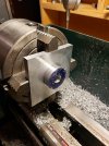
20220722_205535.jpg

20220722_223436.jpg20220722_223436.jpg

Finished grooving the keyed shaft for the cluster gear and got that installed.
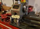
20220723_224416.jpg

Sealed up the headstock by epoxying a short section of 2" conduit inside so the oil-bath bearings don't lose all their oil past the holes on inboard sides of the bearings.
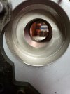
20220723_213358.jpg

Sourced some old automatic transmission parts for material to make seal housings for the headstock bearings.
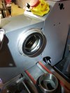
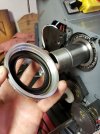
20220723_194911.jpg

20220724_140030.jpg

Then I pressed in new tapered-roller bearings and installed the spindle.

After that I parted the gear spacer in half, polished it for a seal journal, and installed it. I left just enough sticking out past the seal to clear the drive gear while keeping the drive gear as close to the headstock as possible.
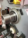
20220724_151524.jpg

Next part of the stack is the drive gear for the leadscrew which had to be repositioned to line up with the future tumbler gears and clear the stud gear. I bored the center out of a 60-tooth gear, cut a key slot, and installed it. Next went the other half of the spacer (which I'll need to drill for the four speed sensor magnets), the pulley, and spindle nuts.
20220724_163750.jpg

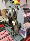
I mocked up the geartrain here. The 60 tooth spindle gear drives either the 25 tooth or 35 tooth rocker gears (for forward or reverse leadscrew direction), the 35-tooth gear drives the 60-tooth gear on the stud shaft which is coupled to the changeable stud gear (here a white plastic 40-tooth), the stud (A) gear drives the compound B gear which is coupled to the compound C gear, the C gear drives the changeable D gear which is keyed to the quick change gearbox input shaft. The compound gears will be mounted on the banjo. Still have to make the rocker assembly and lever, banjo, and some other small parts but this is the general idea of how it will work.
 
Last edited:

Bret4207

At the casting bench in the sky. RIP Bret.
Dang man! And this was preferable to finding an old South Bend or something?!! I think someone just wanted to see if he could make a silk purse out of a sows ear!
 

Petrol & Powder

Well-Known Member
Ian, your skill is amazing but that $2500 savings you mentioned in your first post is being consumed by your time. I think your personal labor rate is going to end up being close to $0.25/hour. ;)
 

Ian

Notorious member
Finally got back to it, Princess' fifth birthday celebrations lasted all weekend and most of Monday so been a bit busy. How does glitter get in my belly button, for cryin' out loud?

Anyway, got the stud gear stud/rocker lever stud thingy made....out of stainless steel no less. Tough to hit the marks because there's no sneaking up on them, must take at least a .005" deep cut each time, .015" is better due to instant work hardening of this miserable stuff. It makes a nice part once you figure out how to deal with the material though. I parted a 7/8" section off with a 5/64" parting blade at 200 RPM in one shot and made three chips about 2' long each, feeding the tool fast and steady. Any less feed and chatter, any more and the 1hp DC motor bogged below the speed controller's ability to keep up.

The stud threads into the side of the headstock, the rocker lever pivots around the shoulder and is held in place by the snap ring (plus it will have a radius slot and bolt/wave spring through it), the stud gear hub will hold the bushings and ride on the stud, being held on by the screw and washer. It will make more sense when I get the hub finished, this is my solution to a complex design challenge due to several conflicting but essential features and some space constraints.

20220802_215428.jpg

Oh, and Brad, you'll be proud of me, this whole thing is METRIC. Egads!
 
Last edited:

Bret4207

At the casting bench in the sky. RIP Bret.
Finally got back to it, Princess' fifth birthday celebrations lasted all weekend and most of Monday so been a bit busy. How does glitter get in my belly button, for cryin' out loud?
Thank you for yet another mental image that I'll carry around in my head forever... ;)
 
  • Like
Reactions: Ian

Snakeoil

Well-Known Member
Tough to hit the marks because there's no sneaking up on them, must take at least a .005" deep cut each time, .015" is better due to instant work hardening of this miserable stuff. I
The secret to machining stainless is to use Cobalt or similar HSS cutters. After you grind the tool, give it a good curl behind the cutting edge to curl the chip. Then just kiss the front of the cutting edge on a wheel set to about 2 degrees for max strength. You can take very fine and accurate cuts. Put a small radius on the nose and your finish will be very nice as well. Carbide bits are nice for production work. At the lab, we all used Cobalt HSS bits ground to our personal preferences. Most of our work was in stainless, Inconel or similar materials. It was all for the nuke Navy.
 
  • Like
Reactions: Ian

KeithB

Resident Half Fast Machinist
Sharp tools always when chewing on stainless. A dull drill will cause more problems than you can imagine. And we've found that no matter what kind of tool material you use there is a speed where everything cuts fine and one notch faster and everything goes to hell in a heartbeat. Got to control my impatience, which is hard to do when you're fighting the clock.
 

Ian

Notorious member
Thanks for the tip on the relief angle for finer cuts, Rob. I've been using my usual HSS cutter grind with about 5 degrees of relief and zero rake angle and it's good for removing material but won't skips and hardens the surface when trying to take a fine cut due to the micro-flex of the mini-lathe. I did try grinding a chip breaker on one of the tools with a Dremel and 1/8" diamond cylinder but found out that's not a small enough radius to help much. Sharp edge and radiused point is the ticket for a good finish, I keep a fine Norton bench oilstone by the lathe and touch up with that as needed.
 

Ian

Notorious member
Go the banjo, banjo stud, quick change lever and gears, and a few dozen other tiny details finished just so I could try this thing out. Spent pretty much all weekend making parts and fitting them up, didn't take pictures of all the parts I turned and milled so I just took a video of the progress. I did go ahead and mount the chuck, change to the threading compound pair, and turn an 18 and 20 thread pitch to verify my ratios before pouring any more effort into this rabbit hole. The toy belts are a no-go, anything more than .005" depth of cut in aluminum causes them to slip when threading and the motor is too weak to be of any real use. I put new bearings in the reduction pulley but they are loaded in a bad bind and roar terribly, I will have to totally redesign the drive belt system using cogged belts, pulleys, and a proper bearing arrangement. The motor and drive system was one thing I was hoping wouldn't have to be totally replaced, but live and learn. The keyed, precision ground shaft I bought from McMaster-Carr is bowed so I need to take apart the gearbox and straighten both shafts to take the wobble out before making the faceplate and detent plunger for the lever. The leadscrew is also bent slightly which strangely doesn't affect the half nut function but is hell on the borrowed threading dial so I'll have to deal with that too.

Excuse the concrete nail....I'll make a proper shift lever detent plunger at some point. It kicked into neutral at the end of the video.

Anyway...

 
Last edited:

Bret4207

At the casting bench in the sky. RIP Bret.
Good job Ian. I just saw a video on YT where a guy changed out the motor and used cogged belts and jackshafts to do it. Didn't watch it, but it's there someplace. I have no doubt you'll figure it out.
 

Ian

Notorious member
I'll look Bret, thanks. I saw one guy who had a 7x14 that was doing an oil-bath headstock bearing conversion and he already had a treadmill motor and speed control unit modified to fit, he probably did a video on it too. This 6" chuck driven by sewing machine belts is a joke.
 

Ian

Notorious member
Been chipping away at my to-do list and growing it just as fast. After ordering more metal, some timing gear sprockets, belts, and capscrews and making a whole pile of new parts I finally got to give the new belt drive and headstock support bracket a go last night.

 
Last edited: