You are using an out of date browser. It may not display this or other websites correctly.
You should upgrade or use an alternative browser.
You should upgrade or use an alternative browser.
South Bend 7" shaper refurbishment
- Thread starter Ian
- Start date
Ian
Notorious member
What's next?
I get to do "subtractive manufacturing", linear-style
Nothing quite like the experience of tearing a machine completely down and finding and fixing all of its problems to prepare a person to learn how to actually USE it. For example, there are two critical oil points for the linkage under the ram that are not shown in the manual, accessed through the slit in the top of the ram, that I probably wouldn't have noticed if I hadn't taken the thing all apart. Also, one observes moderation in tightening the stroke adjustment when they make the parts for it from scratch and realize how easily the ears on the bushing can get bent, and how else would a newbie know the motor ran backwards if he didn't have it all apart and watch a Tubalcain video about the Whitworth quick-return mechanism?
Ian
Notorious member
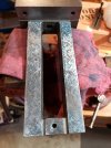
The vise has problems. So did the table. Chips being sandwiched between the vise base and table put numerous craters in both and pulled them convex around the central pivot stud. I got the table reasonably flat again by scraping and stoning, then took apart the vise to measure and study. The vise had a twist to the rails (warpage, I think, not abuse) and a pretty good saddle from wear.
I scraped the bottom of the vise frame flat as a reference point, then scraped the top flat and parallel to it.

My granite plate is AA grade which means flat to something like 80 millionths of an inch, so the blue print on the vise is near that now. I had to correct it from a maximum of .0025" dip in the middle and .0016" sideways tilt. The tilt accounted for the .004" in 4" taper I was getting in my parts, nott to mention all the tolerance stacking from the base to table and base to vise frame. The goal here is to make the blued surface above flat and parallel to the ram ways under load. I also scraped the bottom of the vise base flat to match the table, so now I need to put it all together and tram it to the ram and saddle to check my work. Before I do that, though, I have to set up the vise frame upside-down on some 1-2-3 blocks on my mill table, clamp it carefully so as not to induce warp, and cut the waves and low spots out of the articulating jaw's guide ways on the underside to make them even and parallel to the top of the frame, then mill the jaw itself to restore a very close fit so it doesn't lift when tightened against a workpiece.
I scraped the bottom of the vise frame flat as a reference point, then scraped the top flat and parallel to it.

My granite plate is AA grade which means flat to something like 80 millionths of an inch, so the blue print on the vise is near that now. I had to correct it from a maximum of .0025" dip in the middle and .0016" sideways tilt. The tilt accounted for the .004" in 4" taper I was getting in my parts, nott to mention all the tolerance stacking from the base to table and base to vise frame. The goal here is to make the blued surface above flat and parallel to the ram ways under load. I also scraped the bottom of the vise base flat to match the table, so now I need to put it all together and tram it to the ram and saddle to check my work. Before I do that, though, I have to set up the vise frame upside-down on some 1-2-3 blocks on my mill table, clamp it carefully so as not to induce warp, and cut the waves and low spots out of the articulating jaw's guide ways on the underside to make them even and parallel to the top of the frame, then mill the jaw itself to restore a very close fit so it doesn't lift when tightened against a workpiece.
Bret4207
At the casting bench in the sky. RIP Bret.
Looks good Ian. My Atlas sits on an old heavy steel office desk, solid as all get out actually. I find when it gets going in heavier cuts there are harmonics or something that cause some build of an almost rocking motion. If I slow down or lighten the cut it goes away. Just a thought if you run into it with your movable base.
Let me know what you find when you get going on making HSS tooling for use with out the Armstrong tool holders. I haven't had any luck in that regard at all. The HSS flexs too much without the tool holder stiffening the assy.
Hey, there's a 18 incher (IIRC) up here for sale up here for a few hundred $$. Estimated weight is like 4 tons. You want me UPS it to you?
smokeywolf
Well-Known Member
Not to say they don't exist, but I've never encountered a vise, even a new Kurt, that didn't lift the workpiece at least a little bit, when you tighten down on the jaws. That's why you usually give the workpiece a couple of good whacks with a lead hammer or dead-blow mallet after tightening the vise jaws.then mill the jaw itself to restore a very close fit so it doesn't lift when tightened against a workpiece.
Last edited:
Ian
Notorious member
Good advice, R.J. I do seat the work with a non-marring dead blow hammer and use the paper strip trick or check the tension of the parallels (if using) to verify it seated, but a jaw lifting of only a thousandth makes it easier to seat the part than if the jaw lifts .007" as it does now. I can tighten it up with a little strategic milling, so why not?
Ian
Notorious member
Bret, I'm learning as I go so will find out. I can see that too much tool stick out may be required for the tool tip to clear the bottom of the tool head, but I also see a really deep slot in the tool post and suspect up to two additional 3/8" square pieces of HSS could be stacked together behind the cutting tool to support it on the back side and reduce flex/chatter. I have some burned-up 3/8" x 1" x 3" pipe thread cutter inserts which could be made into shaper tools and clamp in the toolpost just like the Armstrong adapter, should be quite rigid and might be something for you to try?
smokeywolf
Well-Known Member
Didn't realize you were dealing with that much slop in the vise.Good advice, R.J. I do seat the work with a non-marring dead blow hammer and use the paper strip trick or check the tension of the parallels (if using) to verify it seated, but a jaw lifting of only a thousandth makes it easier to seat the part than if the jaw lifts .007" as it does now. I can tighten it up with a little strategic milling, so why not?
I've stacked toolbits in the shaper's toolholder before in order to use a smaller toolbit that already had the shape ground in it that I needed.
Whenever possible, try to have your vise oriented so that the back jaw is perpendicular to the ram stroke. Reduces the possibility of lifting the workpiece out of the vise jaws.
Your rotate feature on your vise looks like it could contribute to a lack of rigidity. Can it be removed? Can your mill vise be clamped or bolted to your shaper table?
Ian
Notorious member
The vise that came with the shaper (it's original) has keyed slots in the base that match the table for perfect alignment in 90⁰ increments, or the key can be pulled and degree marks on the base and marks in the table used for other angles. In other words, it swivels directly on the table. There's not a real good way to mount the vise if the base is removed. A more rigid mill vise could be used and I've thought of that, but I figured I'd fix the problems the original had first and see how it does.
Ian
Notorious member
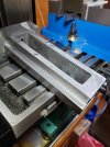
Got the vise frame milled flat and clean where the articulating jaw blocks ride on the bottom. Both rails are parallel to .0001" checking in multiple places with a C-clamp mic, and within .0001" of each other side to side.

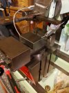
I mounted my mill vise back up and trammed it, tried to get the articulating jaw set up using the clamping face as a reference against the mill vise's fixed jaw, but when I do the surfaces to be milled tram .006-7" out of square with it. That's a LOT considering it's like 2.5" of surface. Grilling some pig for supper and mulling it over....

I mounted my mill vise back up and trammed it, tried to get the articulating jaw set up using the clamping face as a reference against the mill vise's fixed jaw, but when I do the surfaces to be milled tram .006-7" out of square with it. That's a LOT considering it's like 2.5" of surface. Grilling some pig for supper and mulling it over....
Bret4207
At the casting bench in the sky. RIP Bret.
Ian, I've tried backing the tooling up, but it still seems to want to chatter some and if you block it too much the clapper lets it drag excessively IMO. The tool holders I have work pretty good, but they are 1/4". I never seem to remember to look for 3/8".
I didn't get a vise with my shaper. I have a cheapy on there that I'm not happy with. I'd prefer to lock stuff down to the table but I haven't run across a set of 5/16 bolts and wedges I want yet. My Atlas doesn't have a lot of extra room for most of the halfway decent vises I've seen. I have a Palmgren that works okay but there's no swivel at all. Limiting.
I didn't get a vise with my shaper. I have a cheapy on there that I'm not happy with. I'd prefer to lock stuff down to the table but I haven't run across a set of 5/16 bolts and wedges I want yet. My Atlas doesn't have a lot of extra room for most of the halfway decent vises I've seen. I have a Palmgren that works okay but there's no swivel at all. Limiting.
Ian
Notorious member
You have a lathe and a shaper, make yourself a new insert for the Armstrong that accepts bigger tooling.
I finally got the articulating jaw set up in the mill where I was happy with it (shimmed until the jaw plate surface was perfectly vertical) and milled the underside that rides the top of the frame so it was even and square to the face. Then I milled down the bottom surfaces where the guide plates bolt to give a half-thousandth clearance on each side, stoned off the burrs, and out it all back together. Something is still screwy with the vise base because the vise has a .001" in 3" sideways tilt and .002" in 3" lengthwise slope. I know the box table is flat and level because the measurements (tramming with the ram and saddle) repeat in the same direction relative to the vise when the vise is indexed at 0⁰ or 90⁰ either direction. The vise base must be thin on one side, one thing I didn't check. So it continues...

I finally got the articulating jaw set up in the mill where I was happy with it (shimmed until the jaw plate surface was perfectly vertical) and milled the underside that rides the top of the frame so it was even and square to the face. Then I milled down the bottom surfaces where the guide plates bolt to give a half-thousandth clearance on each side, stoned off the burrs, and out it all back together. Something is still screwy with the vise base because the vise has a .001" in 3" sideways tilt and .002" in 3" lengthwise slope. I know the box table is flat and level because the measurements (tramming with the ram and saddle) repeat in the same direction relative to the vise when the vise is indexed at 0⁰ or 90⁰ either direction. The vise base must be thin on one side, one thing I didn't check. So it continues...

Last edited:

