Start of new machining project

KeithB

Resident Half Fast Machinist
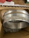
I bid on a project to make some air inlet trim rings and got the job. Here is an example. (I edited the photo slightly to occlude the manufacturer's part ID#.) I made some of a slightly different design for one of our customers, who told another customer, who eventually contacted us. Another word-of-mouth situation.

There are several steps that need to be taken to do this job. (a) I need to find a good way to prepare the material. (b) I need to make a set of round soft jaws for my lathe chuck in four sizes, and (c) I need to make a better CAD drawing of the parts.

The customer who contracted for the first set of rings supplied the material, which was 6061 aluminum tubing. When I bid on the second job I had to include the material cost. It turns out that solid round stock is cheaper than tubing! These inlet rings come in 4 sizes from 3-3/4" to 6" OD and finish at 1-3/4" long. Boring out the center of a solid blank in steps is time consuming and wasteful; the cost of the extra time negates any savings in material cost.

I decided that using a hole saw to remove a plug of material may be the best way to prep the blanks. It can make a large hole in one step, and it doesn't waste much material - the resulting plug can be used to make a smaller size ring! I think I can drill a little over an inch deep from both sides. So I ordered four hole saws and a couple of arbors from our local tool vendor.

When I picked them up the counterman asked me what I was going to do with them and I told him. He looked at the biggest one (5-1/2"), cocked his head a little and asked how I planned to drive it. I whipped out my Iphone and showed him our new toy. He agreed that would probably handle it...

Sample inlet ring
inlet_ring.jpg

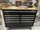
I used $398 of my stimulus money to buy this toolbox at Home Depot. We have several other mobile toolboxes in Husky brand and have been very satisfied with the quality and cost. This is 46" wide x 27" deep, has roller bearing on the drawers, rolls very easily, and has a pretty nice wood top.

Husky tool box
toolbox.jpg

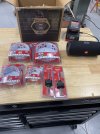
Here are our hole saws. 2-1/2", 3-1/2", 4-1/2", 5-1/2" + 2 arbors.

Hole saws
holesaw.jpg

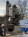
Our new radial arm drill being unloaded. Ought to be a real hole-saw driver!
radial_arm_drill.jpg

Tomorrow I plan to try sawing out a sample blank. I'll post the results.
 

Joshua

Taco Aficionado/Salish Sea Pirate/Part-Time Dragon
At work a few months ago we did 4” and 5” holes in 5/8” 5052 AL. Sheared a 3/8” shanked arbor in half on the first day, chips bound it up. Flood coolant will remove the chips, but you need to constantly raise the hole saw to keep the chips flowing or the saw can bind. Speed is important also, too fast and the vibration is horrible. A hole saw is just a piece of sheet metal, not a very ridgid setup. But, they will definitely cut 1” deep in aluminum.
 

Ian

Notorious member
I thought this sort of thing is what annular cutters are for? I'm guessing the cost vs. premium hole saws is a big factor.
 

smokeywolf

Well-Known Member
Annular cutters are very efficient. Not much beats them for coping two pieces of round tubing to be welded or brazed together in a "T" shape or tangentially. Used to use them somewhat regularly on stainless tubing that was to be welded together. I'm talking 1 to 2" tubing. Makes me shudder to think what a 5" annular cutter might cost.
 

Joshua

Taco Aficionado/Salish Sea Pirate/Part-Time Dragon
In our case the set of hole saws was sitting on a shelf. Ordering tooling that large would be both expensive and would have delayed the project.

Hole saws won’t make a precision hole but they can make a decent hole in metals.

Years ago I used to build Freon receiver tanks out of 6” steel pipe. The receiver tanks were meant to be oriented horizontally under a sea water chiller. They had sight glasses top and bottom. To create the weld joint the holes had to be drilled offset to the centerline of the pipe. You can’t do this with a an 1 3/4” drill bit. The quarter inch center bit hole for the hole saw had to be drilled by hand, you started straight into the pipe and then you twisted the drill motor up vertically. Then the hole saw had a place to start. We did all this in a big radial arm drill press. Everything would be fine until a broken tooth would embedded itself into the steel. Then it was time to break out the cold chisel and chip away until you got the hardened tooth out. Great fun!
 
Last edited:

Bret4207

At the casting bench in the sky. RIP Bret.
I think the brand of hole saw makes a big difference. I like Milwaukee, although I'm not a big fan of their tools. Not sure who makes their hole saws for them, but they are good on steel. I have a drill press equipped with a treadmill motor that I can slow waaaay down. Vibration is a factor no mater what even at slow speeds.
 

KeithB

Resident Half Fast Machinist
Exactly what I found out. Can’t afford annular cutters!

Our new radial arm drill has a wide range of speeds and feeds and all the mass needed for damping out vibrations. I’ll start at about 48 rpm and a moderate feed rate, use flood coolant, and peck drill to keep the chips cleared out.

If you’ve never run a big radial arm drill you just can’t understand how they perform compared to a post drill. Worlds of difference between the two.
 

smokeywolf

Well-Known Member
We had a good sized flat leather belt drive Avey drill press in the MGM shop. Used 3"-4" hole saws in it, running at 30 or 36 (can't remember which) RPM to bore the lightening holes in 2-3,000 ft film reel flanges. Circle cutters could be used, but you had to go half way thru, then flip the part over and finish from the other side or the cutter would have a tendency to nick the OD of the hole as it broke through.

Got a chance to run a big radial arm press once. With the right speed and arm lowered to minimize quill extension, it was more like drilling with a large mill. I don't think anything beats mass for keeping vibration and chatter to a minimum.
When drilling or milling, we used to throw shot-bags, usually on corners or peripheries of parts that could not readily or conveniently be clamped down.
 

KeithB

Resident Half Fast Machinist
Been working on this project the last few days. The goal is to be able to deliver four different sizes of air inlet rings as our customer demands. The process requires safely turning a solid round aluminum blank into a relatively thin walled part without distorting it. It would be nice not to damage the machines and machinists also!

A three jaw chuck will distort thin tubing, a four jaw is better but its slow and still causes some distortion of the part. The best way is to either (a) get a six jaw chuck, or (b) make pie jaws of the proper size. I thought about buying a six jaw chuck but don't have the $1000+ it would cost to get even a moderate quality one. I do have a cheap but rugged three jaw that I can replace the jaws on (the reason I bought it) and when fitted with soft jaws and bored to size it can be amazingly accurate. So I decided to make some aluminum pie jaws in the four sizes (Small, Medium, Large, and Extra Large) of our customers product.

The first step was to saw a dozen 2" x 4" x 7-1/4" blanks from a 12' bar. Then the blanks were put in the CNC mill and the blank was drilled for bolts that would be used to anchor the blank to a fixture for part of the manufacturing process and to anchor the jaw to the chuck slides during use. In order to keep everything aligned and create reference locations two 0.250" holes were also reamed in the blank.

A simple plate fixture was made from a 4" x 6" x 3/4" steel plate. Two 1/4" dowel pins were pressed in the holes and spot welded on the back to keep them from coming loose. (They were a slip fit) A cross bar and two uprights were made from some 1" x 1-1/2" steel bar.

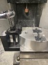
The first step was to bolt down the blank to the fixture using the two center bolts and use a 1/2" stagger tooth roughng type end mill to mill the periphery of the part, leaving 0.015" for finishing. The endmill will only cut about an inch deep so the part was flipped over and the same program was run again.

After all the parts had been roughed out a brand new 1" diameter x 2.25" flute (cutting) length end mill was used to cut the entire 2" thick blank in one finishing patch. (The endmill cosr $205. OUCH!) 300 rpm and 0.008"/rev feed rate.

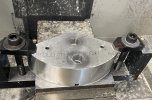
The third step was to attach the clamping bar to the fixture and use toe clamps to hold the edges of the part while the middle of the part was being worked on. One side got the flats and keyways and mounting surfaces milled to key it to the slides in the chuck. I was able to cut things to a pretty close tolerance so that the jaws fit snugly but only need a light tapping with a rubber mallet to fit in place.

The fourth and final step was to counterbore the top side for the cap screw heads. Since I didn't have the right size counterbore tool I used the same 1/2" roughing end mill that I used to rough out the part. The hole need to be about 0.680" diameter so I just ran the mill into the center of the hole, fed it down 0.1", fed it sideways (X axis) by 0.090", ran it in a circle with a 0.090" radius, and then fed back to the center. Rinse and repeat 14 times and you have a 1.4" deep counterbore. Actually, since that mill only has 1" of cutting edge I fed it down 0.6" while makin a 0.75" diameter hole and then an additional 0.9" making a 0.680" hole. That's why there is a little step in the hole.

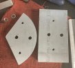
Drilled blank on right, profiled blank on left
pie_jaws01.jpg

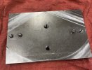
Basic plate fixture
pie_jaws02.jpg

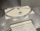
Blank profiled halfway deep. The part is then flipped over and the program rerun.
pie_jaws03.jpg

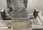
Fixture with clamp bar mounted
pie_jaws04.jpg

Loosening a toe clamp after cutting the keyways and mounting surfaces
pie_jaws05.jpg

Part after being counterbored for cap screw heads
pie_jaws06.jpg

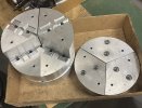
The bottom (left) and top (right) of four sets of 8" pie jaws ready to be mounted and cut to fit
pie_jaws07.jpg

Here is a set mounted on an 8" chuck
pie_jaws08.jpg
 

KeithB

Resident Half Fast Machinist
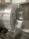
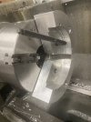
With the jaws mounted I decided to make the jaws to fit the largest part - 6" OD - and make a sample/demo part. The first step was to bore out the jaws. I clamped a 3/4" rod in the jaws to take the slop out of the scroll and slides and keep the jaws from bouncing around. It also gives me some extra material in case I ever need to recut the jaws. Just put in a little smaller clamping rod, recut the jaws, you're good to go.

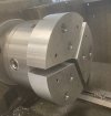
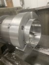
The jaws were bored out to 6.000" diameter x 0.812' deep, with a 5.500" diameter bore cut another 1/8" deep to provide tool clearence for boring out the part. One of the photos shows the cross-section of the finished jaws.

I used a scrap piece of 6" aluminum (6061-T6) round stock to make a blank that would be identical to what I will get when I saw a blank off a longer section. (For this project we will buy our round stock in 6' long sections.) I had to square it up and shorten it until I had a 2" long section.

I tried holesawing a plug out but soon realized that driving a 5-1/2" holesaw using an arbor via a 3/8" hex shaft was a good way to see things explode. I plan to make a better mounting and drive system and try again but for this one part I just drilled a 1" hole and bored the blank to size in steps.

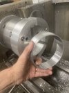
The jaws worked perfectly. I was able to make the part in two steps with no real issues.

I made the other three sets before I knocked off. Tomorrow I'm going to dig through our scrap bin and see if I can find some pieces I can use to make the other three size parts. I would like to send a complete set to our customer for approval before we start making things for money.

Finish bored 6" soft jaws
pie_jaws09.jpg

You can see the cross section well here
pie_jaws12.jpg

The part at the end of the second operation
pie_jaws10.jpg

The finished part
pie_jaws11.jpg
 

smokeywolf

Well-Known Member
Nice Keith. I've always been a fan of soft jaws. Bored properly using the right size round or a lathe cam that hasn't been abused, soft jaws will oft times repeat within 2 or 3 tenths.
I always wanted a Buck Adjustru or Bison Set Tru 6 jaw.