KeithB
Resident Half Fast Machinist
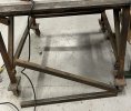
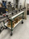
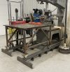
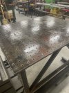
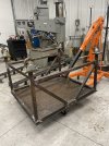
I have a steel welding table. The top is a 3/4" thick piece of medium carbon steel measuring 48" long and 40-3/4" wide . The frame is primarily 1-1/2" x 12 gauge square tubing, with four heavy duty metal wheels that allow it to be moved when needed.
I have always wanted to drill and tap a grid of holes on the top that could be used in conjunction with other hardware as a way to clamp things down, but up until recently I had no practical way to do so. The only way to hold things to the table top is to (a) use vise grips and C-clamps if you're within a few inches of the edge of the table, or (b) weld something to the table top and cut it back off later if you have to clamp something on the interior of the table.
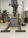
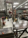
A couple years ago we bought a medium size radial arm drill (48" arm, 12" column) and that was just what was needed for this project. The only trick was to get the table under the drill head.
As I looked at this project I knew it would be a lot of work, especially for someone with the health history and challenges I've been facing, but I also knew that if I broke this project down into several discrete steps I could accomplish each one w/o feeling overwhelmed.
I broke the project down into the following steps:
1. Accurately locate the holes on the table surface.
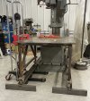
2. Get the table under the drill head.
3. Drill, chamfer, and tap the holes
It turns out I had to add several steps:
4. Cut the supporting frame loose from the top and reweld it into a better position.
5. Drill and tap the holes that couldn't be done in step 3.
The first thing I did was try to figure out the easiest way to accurately lay out a grid of holes. I decided that the holes should be on 2" centers. Since that would mean 480 holes in the 20 x 24 hole grid I did not want to use a scriber and center punch.
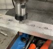
I decided to make a drill jig using a piece of 3" x 3/4" x 48" aluminum flat stock. I used a two vise setup to hold the bar straight on the mill table. My mill only has 30" of travel so I drilled and reamed as many holes as I could, then I moved the piece down and realigned it with an alignment spud mounted in the mill collet. This let me finish up the rest of the holes. Measurements taken to holes on either side of the "jump" show very close accuracy.
Drilling the bushing bar using a two vise setup on the manual mill.
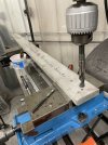
Reaming the holes to 5/8" to match the drill bushing OD
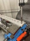
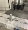
I could only do about 2/3 of the holes so I had to move the bar to drill the remaining holes. I used an alignment stud I made to locate a hole to re-zero to drill the rest.
The alignment spud out of the collet
I bought a couple hardened drill bushings off eBay, the OD is 5/8" to match the holes in the bushing bar, the ID is 27/64", the tap drill size for a 1/2-13 thread.
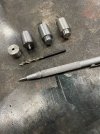
I also made several drop-in alignment bushings. One has a 5/8" OD and a short 0.125" diameter pin. Another has the same OD but has a 0.125" diameter hole. These will be used to help layout the first holes. Two more bushings with a 5/8" diameter on one end and a 27/64" on the other will be used to pin the ends of the bushing bar to the corner holes in the table.
The tools used to layout the holes.
The first step was to lay out a scribed line parallel to one of the long edges of the plate. I tried to make sure it would be the right distance away so the line on the far side would be the same distance from the far edge. Then I layed out the position of the first end hole, again making sure it would center things up. I made a small punch mark and then drilled an 1/8" hole using a hand power drill. I dropped in the bushing with the 1/8 projection and went to the other end of the bar. The bushing with the 1/8" hole was dropped into the bar and an 1/8" hole was drilled through it into the table.
Now that there were two holes, one on either end of the table, it was time for a little plane geometry. I pinned the bar down on one end and using the bushing with an 1/8" hole (yes there was a reason for that size, it it the same diameter as the carbide tip on my scriber) I scribed an arc on the tabletop. I then moved the bar to the other end and scribed another arc. This was enough to be able to scribe a straight line parallel to the first line, but not enough to be sure the grid was square and not skewed. I calculated the diagonal distance across the corners and using a steel tape layed out the place where the lines crossed at the corners. When I measured the distance between the intersecting lines they were very close to the exact distance needed, and by judiciously "fudging" I was able to get two punch marks in the right place. After drilling 1/8" holes at each location I was able to pin the bar into any of the holes and have it line up with the other corner holes. This was enough to allow the bar to be pinned into place for drilling. On to step 2.
The bushing bar clamped in place ready to start drilling the corner holes
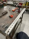
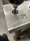
Drilling the initial 1/8 hole.
I have always wanted to drill and tap a grid of holes on the top that could be used in conjunction with other hardware as a way to clamp things down, but up until recently I had no practical way to do so. The only way to hold things to the table top is to (a) use vise grips and C-clamps if you're within a few inches of the edge of the table, or (b) weld something to the table top and cut it back off later if you have to clamp something on the interior of the table.
A couple years ago we bought a medium size radial arm drill (48" arm, 12" column) and that was just what was needed for this project. The only trick was to get the table under the drill head.
As I looked at this project I knew it would be a lot of work, especially for someone with the health history and challenges I've been facing, but I also knew that if I broke this project down into several discrete steps I could accomplish each one w/o feeling overwhelmed.
I broke the project down into the following steps:
1. Accurately locate the holes on the table surface.
2. Get the table under the drill head.
3. Drill, chamfer, and tap the holes
It turns out I had to add several steps:
4. Cut the supporting frame loose from the top and reweld it into a better position.
5. Drill and tap the holes that couldn't be done in step 3.
The first thing I did was try to figure out the easiest way to accurately lay out a grid of holes. I decided that the holes should be on 2" centers. Since that would mean 480 holes in the 20 x 24 hole grid I did not want to use a scriber and center punch.
I decided to make a drill jig using a piece of 3" x 3/4" x 48" aluminum flat stock. I used a two vise setup to hold the bar straight on the mill table. My mill only has 30" of travel so I drilled and reamed as many holes as I could, then I moved the piece down and realigned it with an alignment spud mounted in the mill collet. This let me finish up the rest of the holes. Measurements taken to holes on either side of the "jump" show very close accuracy.
Drilling the bushing bar using a two vise setup on the manual mill.

Reaming the holes to 5/8" to match the drill bushing OD

I could only do about 2/3 of the holes so I had to move the bar to drill the remaining holes. I used an alignment stud I made to locate a hole to re-zero to drill the rest.

The alignment spud out of the collet

I bought a couple hardened drill bushings off eBay, the OD is 5/8" to match the holes in the bushing bar, the ID is 27/64", the tap drill size for a 1/2-13 thread.
I also made several drop-in alignment bushings. One has a 5/8" OD and a short 0.125" diameter pin. Another has the same OD but has a 0.125" diameter hole. These will be used to help layout the first holes. Two more bushings with a 5/8" diameter on one end and a 27/64" on the other will be used to pin the ends of the bushing bar to the corner holes in the table.
The tools used to layout the holes.

The first step was to lay out a scribed line parallel to one of the long edges of the plate. I tried to make sure it would be the right distance away so the line on the far side would be the same distance from the far edge. Then I layed out the position of the first end hole, again making sure it would center things up. I made a small punch mark and then drilled an 1/8" hole using a hand power drill. I dropped in the bushing with the 1/8 projection and went to the other end of the bar. The bushing with the 1/8" hole was dropped into the bar and an 1/8" hole was drilled through it into the table.
Now that there were two holes, one on either end of the table, it was time for a little plane geometry. I pinned the bar down on one end and using the bushing with an 1/8" hole (yes there was a reason for that size, it it the same diameter as the carbide tip on my scriber) I scribed an arc on the tabletop. I then moved the bar to the other end and scribed another arc. This was enough to be able to scribe a straight line parallel to the first line, but not enough to be sure the grid was square and not skewed. I calculated the diagonal distance across the corners and using a steel tape layed out the place where the lines crossed at the corners. When I measured the distance between the intersecting lines they were very close to the exact distance needed, and by judiciously "fudging" I was able to get two punch marks in the right place. After drilling 1/8" holes at each location I was able to pin the bar into any of the holes and have it line up with the other corner holes. This was enough to allow the bar to be pinned into place for drilling. On to step 2.
The bushing bar clamped in place ready to start drilling the corner holes

Drilling the initial 1/8 hole.


