That's funny, because years ago, that's why I put a PID on my lead pot. I had the electronics on hand and a thermometer was something like $50. Easy to read at a glance and easy to read from the other side of the garage bay (16') so I can tend to other things as the pot comes up to temp.I got one for my pottery kiln to use for heat treatment. So far all I used it for is the thermometer, the kiln's own control box is plenty accurate and consistent for what I need as it turns out.
You are using an out of date browser. It may not display this or other websites correctly.
You should upgrade or use an alternative browser.
You should upgrade or use an alternative browser.
Any "MY PIN" PID Controller, Builders Here?
- Thread starter seagiant1
- Start date
Hi,
Yep, I noticed that the TC connectors/plugs, were not exactly cheap, trying to build this controller as frugal as possible.
I went with the MY PIN PID, as it was not the most expensive, but not the cheapest either, and can be switched to read F degrees!
Yep, do that - build it as cheaply as possible. You can always add to it if you want - or not. Mine got "fancier" by degrees over a long time. I even used old TCs which were not ideal for a long time, but they were free.
Anybody can throw a bunch of money at something and make it functional, but it's more fun to challenge yourself and see how little you can get away with and still accomplish what you want to.
I used mine for a long time before springing for the plugs, because they seem a bit costly for what they are. Everyone's preferences and needs differ and will dictate what they use. I'm sure some see the electronics as a ridiculous and unnecessary expense and complication, but for me, I was being as frugal as possible myself. I had the stuff already (picked it out of the trash, for the most part) and it was cheaper than buying a thermometer.
EDIT: It just occurred to me - the box I put my controller in was a "FUBAR" from a friend's business, who I hired to help when I was overwhelmed. I asked if they had a box that they'd messed up and were going to scrap. He asked what I was doing (not nosey, but interested in the project) and I explained. "Why not just buy a new box so it looks nice," was the reply, and he'd have sold me one cheap or I could have gotten one at cost from my supplier, but my reply was "because it has to be free or cheap for the principle of it." He laughed and found me a box.
Last edited:
hporter
Active Member
I noticed that the TC connectors/plugs, were not exactly cheap
The ones I used are around $4 a piece.
https://www.omega.com/en-us/tempera...l-connectors-and-assemblies/rmj-rsj/p/RSJ-K-R
Not bad at all and Omega is trustworthy product.Of course I didn't notice they had zero stock. Sorry.
There are other connector vendors though, and they shouldn't cost much.
By the time I found the ones I wanted, got both parts - in minimum quantities and paid shipping for four sets, I was in over $20.
No, not that much spread over years, but there's that "principle" thing at play sometimes too. How much can I do for how little?
I think I ended up finding an eBayer for mine, along with new TCs and a reamer to remove 35 cal gas check rebates from moulds. Sort of went nuts that spring and spent a few bucks on my casting stuff.
seagiant1
Active Member
Hi,
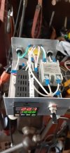
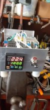
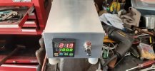
Well I got it made and it actually works!
It is nice when you turn it on and grab the TC and watch the temp start rising and you know it works!
Also good not to see any "Magic Smoke"!!!
Wasn't really that hard but, wanted a good Blueprint for the wiring and lay out and found it.
Made the feet out of some round nylon bar and did not use any fuses, I have modern wiring in my workshop with 120V GFIC receptacles.
Now I will program the PID and off to the races...
Thanks to everyone, for help and ideas, it did help!!!


hporter
Active Member
Good job. Looks nice and very clean.
I thought about not putting my circuit breaker in, but sometimes the breakers in your panel don't trip, so I figured it wouldn't hurt. But since you have newer electrical equipment, that wouldn't have been an issue for you.
I also considered the on/off switch. But I used the logic that if the display was on - it was on.
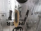
Is that a TC plug I see in yellow on the back panel? How did you decide to do that?
seagiant1
Active Member
Hi,
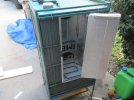
I went the plug route because, I want to use the controller not only with the Lead Pot but also for my homemade Gun Kote Oven. ( I Hobby Gunsmith)
It has to stay at 250 degrees for 2 hours to bake the gun finish a well as preheat parts before spraying.
I used a smoker heating element for the heat source, but the thermostat runs up and down all over the place, and...
Last time I used it I had to babysit it so as to not burn anything up, which gets old pretty quick.
With the plug, I can just install and leave the TC on each piece of equipment I use the control box on.
TC's, are cheap enough!


Last edited:
seagiant1
Active Member
Last edited:
seagiant1
Active Member
Hi,
Ok, I took the PID Controller for a spin and had a problem, but figured it out and thought I would mention it to maybe help the next guy using a "MY PIN" PID.
When I hooked the Controller up to my RCBS Pot, I had the temp on the Pot set to WOT or 850 degrees.
I set the set temp to 700 degrees on the Controller and the Controller would not ramp up the Temp, it would just sit there or even drop.
Got my VOM Meter and checked the out put voltage from the Controller and it was 120V, but still the pot would not come up in temp.
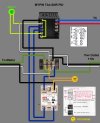
Reversed leads on TC and no good, then I went back to the print I used which I will show and noticed some conflicting info.
On the SSR you have pins 3 and 4, they are marked, +3 and -4, however on the schematic for the PID pins 3 is a neg. and 4 pos.???
So seeing nothing to lose, switched the leads to the SSR and the Controller now works correctly!
Just thought that might help someone down the road!

seagiant1
Active Member
Hi,did you connect the chassis ground to the 120v neutral on the SSR?
Kind of hard to see in photo?
I drilled a hole in the back of the box and put round hole crimps on both ground wires from the cords and then screwed them both together with a screw.
That way not only is the Pot grounded but also the Aluminum Box to help me avoid a shock, touching it ,if there is a problem.
I see no neutral on the SSR, unless you are talking about the Neg Pin?
Last edited:
No neutral on the SSR, just + and - for the signal and the HOT (120V), which you are switching.Hi,
I drilled a hole in the back of the box and put round hole crimps on both nuetral wires from the cords and then screwed them both together with a screw.
That way not only is the Pot grounded but also the Aluminum Box to help me avoid a shock, touching it ,if there is a problem.
I see no neutral on the SSR, unless you are talking about the Neg Pin?
I remember a point in an electronics course 30+ years ago, when the professor cleared up a bit of confusion by tracing the connections on a circuit, with his finger on the chalk board, from the power source and back. He pointed at each terminal of each element in the circuit, noting "positive to negative to positive to negative to positive....."
The other thing I remember about that course was that we knew it was break time when he stood at the front of the class and lit up a cigarette before walking out.
L Ross
Well-Known Member
Heck, I remember building a TV in High School, (oh and that one girl in the class didn't wear under pants), and there was a mnemonic that went, Bad Boys Ravaged Our Young Girls Behind Vector Garden Walls. It had to do with little paint stripes on some electrical part, resistors maybe?
Anywhoo, I went from that pinnacle in my electrical knowledge to knowing the nipple looking bump on a D cell battery is the positive end.
Anywhoo, I went from that pinnacle in my electrical knowledge to knowing the nipple looking bump on a D cell battery is the positive end.
seagiant1
Active Member
Hi,
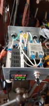
If you look good at this pic, you can see that the ground wires go to the back and secured with a bolt.
I'm not an electrician but try to get by, and why I need good schematics and info to get me home!
Some people just take the ground wires to the terminal block which basically joins them but will not ground the box.
Electricity takes the easiest path and sometimes that is you!


