Titanium Silencer on a Form 1

Pistolero

Well-Known Member
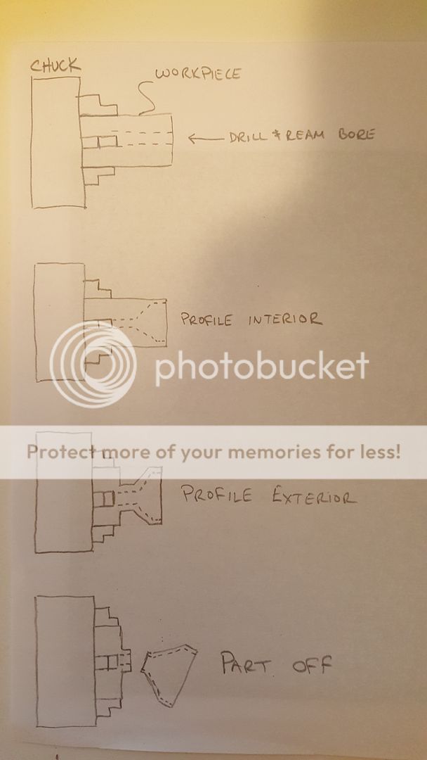
OK, I apologize for my dumb comment, but I thought that the issue was the cylindrical wall
thickness - which is what the pics were showing being cut. Now I understand it is the cone
wall thickness, not easily measured.

I do like Brad's idea of carefully laying out and cutting a template/gauge. If you laid it out in
about 1/16th inch flat steel, carefully measuring and scribing the lines and then cut and finally filed to
accurate shape, you could just cut until the gauge would drop into the part properly. If you were
trying to hold .001 tolerances, not so good. But, as I understand this, you just need to be about
.035 wall thickness and being off by .005 is OK, as long as you don't cut through.

Given that you are going to make more than one part, for me, the time spent on the gage would be
worth it. But the opinion of a rank novice isn't worth all that much! :)

Smokeywolf - I have, in the last year, fully disassembled a Rem Mod. 11 and a Win Mod 97 shotguns.
The bolts on those guns are a real masterwork of metal cutting. Both are almost like a block of
Swiss cheese, except that the "holes", coming in from ALL sides, are all complex shapes, with multiple
parts intersecting, passing each other and sometimes one locking another part in place. That John
Browning imagined these designs without solid modeling software, and finally - that the machinists
could manufacture them at a cost that could be repaid by the sale are both minor mechanical
miracles. Browning was a true genius, no doubt, but he sure put a lot of difficult work on the
guys who had to make those guns. The lifters (carriers) of both designs are similarly complex
machined parts, with the Rem 11 (Browning Auto 5 clone) being a fixturing exercise as 90% of the metal is removed,
and the Win 97 more like the bolts, a block with all sides machined into complex shapes and
then myriad of holes and slots cut through, some blind, many intersecting.
Look at a modern pump gun like the ubiquitous Mossberg 500 (almost the same as the High Standard
Flight King series, and several other designs that are nearly identical) and you find that the real
genius there is that their design is so incredibly simple, very low parts count, each part is very
simple (cheap) to make, yet the gun works very well. Compare the machining cost of a Win 97 to
a HS Flight King, and you have to have at least 3 times the machining time in the Win 97, and some
really difficult cuts, too. Can't remember any specifics now but at the time I was puzzled how
you could even make some of the cuts. They seemed superficially impossible, actually as much a
measure of my ignorance of machining than anything else.
 
Last edited:

Phil

Member
Very nice work on the can.

I have the brother of your Atlas lathe. Bought it about 30 years ago. It was "new" still in the shipping crate. At the time one could still buy accessories from Clausing. I bought most of them. It has served me well.
 

L1A1Rocker

Active Member
L1A1Rocker, please don't take my advice as criticism. It is not meant that way. My suggestions are merely what I would do from what I know of your tooling, lathe and the parts you are trying to turn out.
I've seen people finish an apprenticeship with less knack, talent, know-how than you obviously possess.

The mandrel I had in mind would resemble one of these...
View attachment 785 forgive the dirt, they've been sitting in a cardboard box on the floor for the last 13 years.
Another set of expanding mandrels in a wood block...View attachment 786

Start with...
  • Round stock; little larger dia than O.D. of part, steel or aluminum, turned to within 20 to 30 thousandths over finish dia. (inside dia. of skirt area) of cone.
  • Drill and tap mandrel nose for allen cap screw. Allen wrench must be able to fit through hole in cone; that is what determines size of allen cap screw used in end of mandrel.
  • Countersink end of mandrel using 60 degree center-drill, center-reamer or countersink.
  • With band saw, slitting saw or hack saw, cut 4 or 6 slits in mandrel as seen in pics.
  • Deburr mandrel threads where slots were cut through. I usually fold a piece of wet-or-dry or emory and slide it through the slots, then run the tap back in and out.
  • In chuck or collet, (if chuck, pad the jaws) using compound, turn taper on allen cap screw to match C-sink in nose of mandrel.
  • Mount mandrel in chuck. (With Sharpie, I sometimes put a witness mark and jaw number on the mandrel so I can remove mandrel from chuck and still have a chance of putting it back at a later date fairly close). Make sure mandrel is far enough out from chuck jaws so that jaws won't interfere with machining of workpiece.
  • Screw your 60* allen flat head into mandrel.
  • Tighten allen screw just snug enough so that it won't back out during finish cut(s) on O.D. of mandrel.
  • When turning O.D. of mandrel to finish dia. make sure surface finish is as good as you can get. This reduces chances of part spinning on mandrel during turning/facing operations.
Ideally, you don't want to remove the mandrel from the chuck until all profiling operations have been finished.

ICH, depends on the size, jaw configuration and quality of the chucks you're working with.


Thank you Smokey. I really appreciate you attempts to help. Sorry for being too sensitive. I often forget that the written word does not always convey the correct emotion or sentiment that the spoken word carries. Again, my apologies Sir.
 

L1A1Rocker

Active Member
Good advice above. As a beginner, I am learning too. Would a 4 jaw check be advantageous instead of a 3 jaw to get the part back as close as possible if it has to be taken out for measurements? Thanks and sorry if this is considered a thread hi-jack.

Now worries. The critical deminisions are the O.D. and the hole at the tip of the cone. The less critical is the wall thickness. This baffle will be the "blast baffle" taking the brunt of the blast. So you want this one to be a bit thicker. I'm shooting for .o65 to .07. The alignment for cutting the inside of the cone really only needs to be within a few thou.
 

L1A1Rocker

Active Member
Since my lathe experience consists of having been close enough to at least three of them to notice that they exist as I walked by, I have no idea of the particular challenges involved when actually putting bit to metal. This is an interesting puzzle though, and I bet that with a good pair of Swiss 6" calipers, three hands, and 1" micrometer standard I think I could get pretty close to measuring the thickness of the angled part. It would be best to have a standard with a point on one end. Some math could be done on the chord length of the inside diameter where you put the standard, since a flat-ended standard wouldn't touch but on the edges. I have to measure weird shapes at awkward angles frequently at work, so one has to get creative. The fixed jaw of the calipers would be placed between two of the chuck jaws and flat against the outside of the cone. The moveable jaw would be brought up against the standard and applied to the inside of the cone, and the necessary subtractions done from the measurement.

Are all the baffles going to be cones with integral spacers? If so, when you get out of the weeds on this one, wouldn't T-Rex's method be easier for you on the remaining cones? It seems like it would solve jaw pressure distortion issues as well as simplify the measuring of the cone thickness.

20150902_192107_zps1nmqhz8g.jpg


I understand that your tailstock won't allow the full length of the remaining workpiece to be put in the chuck like the drawing, but I was thinking maybe that little three-screw support thingy you have with the rollers added might work and you could still accomplish the same thing. Is there a vibration issue with that vs. working close to the actual chuck?

I think I see where you are going with that! I have a 1inch round standard that may work.

What T-Rex posted was very interesting. The only problem I see with it is the hole at the tip of the cone. While doing this machining I discovered a bit of drill deflection on my cone. It's not an issue the way I'm currently doing it, but it could be doing it T-Rex's way. I sometimes think it might be worth selling this lathe, and getting a Griz 12X40 gunsmith setup. . .
 

smokeywolf

Well-Known Member
Sorry for being too sensitive.

No apologies. I often have a very dry way of expressing my thoughts.

In case I didn't make it clear before, in my estimation, what you are able to do with a lathe that is geared more toward the hobbyist, shows that your skills as a machinist are much beyond that of the home hobbyist.
 

L1A1Rocker

Active Member
No apologies. I often have a very dry way of expressing my thoughts.

In case I didn't make it clear before, in my estimation, what you are able to do with a lathe that is geared more toward the hobbyist, shows that your skills as a machinist are much beyond that of the home hobbyist.

Thank you Smokey, that's very kind and generous of you.

Well, it's just a touch over .07 but I think it'll be fine. I'll probable turn down a jig with a 60* cone on it to sand the inside down a bit. The cone on the right is the next one that I need to carve the inards out of.


Here's a pic of the two cones together.


I don't know how well you can see it in this picture. But this is looking down the bore at the second baffle inside the blast baffle.


Well, time for bed.
 

smokeywolf

Well-Known Member
Really and truly fine work. And, except for the fact that my L.S. Starrett 1" standard is about 70 years old, it sure looks like yours.

Bedtime? I just mixed up a margarita, made up a batch of rub and threw 2 racks of babybacks, 2 pork tenderloins and a tri-tip on the smoker. Mrs. smokeywolf is going to stir-fry some asparagrass (misspelling intentional) in garlic olive oil and she and I and our monster teenage boys are gonna chow down about midnight-thirty.

This is not unusual behavior for us post-game night during high school football season.
 

L1A1Rocker

Active Member
Smokey, sounds like a great time was had by all. GREAT food! I few months ago I tried some of those big spare ribs in the smoker. Took about 4.5 hours and they really came out great. Two Christmases ago I got an electric smoker, and I'm REALLY liking that smoker. One of my favorites is pork shoulder for pulled pork sandwiches. Only problem with that is I have to be up around 4 am to get it going.

OK, I've completed the other baffle.


Both of the baffles are a bit on the thick side but not so thick that I could make another pass on the lathe and have a decent finish. So I'm making a jag (or is that jig?) that I can put some sand paper on and "fine tune" the thickness of the baffles.


Nothing fancy, just some aluminum roundstock I had on hand. LOL, notice the marks on the round stock? That's from way back when I was contemplating the ACME threads for the muzzle brake.

G'nite folks.
 

Ian

Notorious member
Sweet. I had my doubts about that second cone holding in the chuck near the end as it got really thin but I guess Ti is stronger than I think it is.

All this talk about food got me thinking about that pulled pork you made the other day, DANG that was good. We'll have to have you back for some more riblets or something soon.
 

L1A1Rocker

Active Member
Sweet. I had my doubts about that second cone holding in the chuck near the end as it got really thin but I guess Ti is stronger than I think it is.

All this talk about food got me thinking about that pulled pork you made the other day, DANG that was good. We'll have to have you back for some more riblets or something soon.

Yeah, I would have been concerned too had I not seen a number of posts with folks doing it. That titanium is some tough stuff.

I've been doing a bit of clean up and fitting today. Here's how the parts I've got so far fit together, sorta.


Ian

Notorious member
That looks really good. Amazing how much time, money and thought has to go into those parts. How many more to go?
 

L1A1Rocker

Active Member
That looks really good. Amazing how much time, money and thought has to go into those parts. How many more to go?

I need to cut a section of tubing to thread. I'll do the internal threading on that to match the endcap in the picture. THEN, I'll be able to make the other endcap using that section of tubing as my "gauge". Then there are four K-baffles that need to be made. I'm honestly thinking about making the last two K's out of 6061 aluminum as I'm starting to run low on my allotment of titanium for this can. After that I'll use my three hands to butt it all up together and measure exactly how long the tube needs to be. Then cut and thread the tube. Then engraving. Then find a buddy that knows something about anodizing. . .
 

Ian

Notorious member
What, no VHT header paint? :p

I have hacked my way through a type 1 aluminum job or two, but never anything made of titanium. A constant-voltage power supply would be essential to get the color correct as I understand it. If you want greens it will take a high-dollar one.
 

smokeywolf

Well-Known Member
A lot of people are unaware that titanium can be anodized.

I wanted so much to take the pantograph with me when I closed up the machine shop at the studio. Could have done your engraving for you. Timber, "the goofy wolf" in my avatar needs a new dog tag. Also used to use the pantograph to generate cams for camera movements.
Lay out a heart shaped cam on a piece of 3/16 aluminum sheet. Cut it out on the band-saw, file and sand to the layout lines, then put it up on the pantograph and reduce the 8 inch cam pattern down to a 1/2" cam, cut from Starrett stock (O-1). Heat treat, polish, send it out for salt bath nitride, polish again and viola, cam for shuttle forks which move film through camera movement one frame at a time up to 30 frames per second.

Couple of of other things a lot of folks don't know, anodizing is actually a very thin (usually about .0001) layer of ceramic plating. Also, it is possible to have anodizing infused with Teflon to provide a very good low friction sliding surface.

Sorry for the thread drift.
 

Elkins45

Active Member
Learning a lot from this thread. I'm sitting on two unbuilt Form 1's, one for a 7" 22 and another for a 10" 45. Ian, where are you planning on buying your threaded tube from?
 

L1A1Rocker

Active Member
Well, I've been doing a bit of work on the rear endcap. I've bored out the attachment point where it is to screw on to the silencer and just finished the shoulder that makes the sealing surface.

Smokey, I've got a question for you sir. Looking at the angled surface; The compound is fed manually so I normally sand the surface down. But I'm really happy with how this turned out. Do you think it needs a bit of sanding? I ask because I'm trying to weigh the risk of rounding any edges vs. getting a really slick surface. Your input would be much appreciated. Here's the photos. . .


And for S and Gs here's a photo from way back when I was learning about these threads. This is a peace of delrin that was machined out like the endcap, and then sectioned. It is screwed on to a peace of steal that was machined like the muzzle brake. This does a real good job of showing how the two screw together and form a seal on the shoulder. You can also see that, in the photos of the endcap, the shoulder seems to be very large; but once the threads are cut (as in the delrin model) it's not really that big.


Next step, provided there is no sanding of the matting surface done, is cutting the ACME stub threads in the endcap.
 

L1A1Rocker

Active Member
I am finally done with the rear endcap.


The following pic is looking at the back side. The threads are a bit jagged and rough so I'll need to do a little clean up on that.


Endcap next to the muzzle brake.


Screwed onto the muzzle brake.


Looking from the back side.


Looking from the other direction,


And with the support ring in place.


I think I'll start on the other endcap next. But I've run into a pretty big problem. The A/C in the shop stopped working last night. :(

It's a big 17,800 BTU 220volt, through the wall mounted unit. Not cheap to replace. I'll call around Monday to see if anyone in the area will look at it to see if it's economical to fix it.
 

L1A1Rocker

Active Member
Thanks for the move Brad! I'm going to reconstruct a post from Ian that was relivent to the thread, and my response to keep things flowing correctly here. Again, thank you for moving this over to the correct place and fixing my mistake.

Man, I'd been hanging on to an old 220V, 23K btu unit for about a decade and just gave it away to get rid of it about a month ago. It worked fine but was old, ugly, and by today's standards inefficient. What (generally) quit? Fan, compressor, thermostat?

That muzzle thingy looks really good. I have a question about the support ring: Are you going to drill a whole bunch of vent holes in it, or is the blast chamber just going to depressurize back through the muzzle device?

Darn my luck! If the lucky recipient of your fine generosity is not using it yet. . . . lol

It made a very loud noise like the compressor was engaging - but much louder than normal, and kept making that noise for about 3 seconds. Then the noise stopped and the fan ran, but at a low speed. I shut it off for a while and then turned it on to fan. The fan did not come on and I could hear a loud hum.

Regarding the muzzle. No holes in the ring. I'm keeping a separate blast chamber. With this design the muzzle brake will work as the first two baffles and take the brunt of the blast. The muzzle brake is considered a sacrificial peace as it can be replaced easily, and without any BS from the ATF.