Titanium Silencer on a Form 1

F

freebullet

Guest
Intriguing information here. This is shaping up to be a very high quality build.

I'd considered building one however, without a lathe or mill it seemed like it would be heavy, clunky, and possibly not worth the price & drama of admission. I can cut, grind, weld, & drill but, info on this subject is scarce without precision tools.
 

minmax

Active Member
Check out NFA Talk, form 1 Suppressor, SD TACTICAL fourm, for information about how to assemble without a lot of tools. Also there are a lot of you tube videos out there. Remember video can not capture true sound of the silencer accurately. You can build a silencer for about $150 -$300. I bought an NFA Trust over the weekend for $47×$10 for editable fields in word doc. 199 trust had them on black friday sale. Now just to file my fourm 1.
 

L1A1Rocker

Active Member
Ok, I guess it's way past time to do some more posting. Sorry folks, I've been doing a lot more "doing" lately and not much posting. I wanted to get this project done by Christmas. . .

When last we left off, I was moving to making the K baffles.

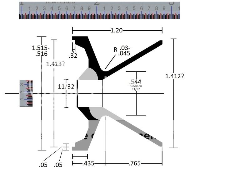
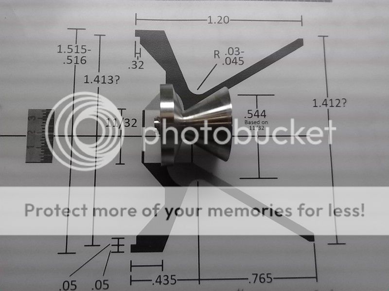
Here's one of the sketches I did - it's not the one I wound up using, but it's close enough, and already on my photobook acct. You'll see the relevant changes as we progress.


Also I need to note a change. I had originally planned on this being a 100% Titanium build. BUT, I was running out of titanium so I made an executive decision. The last two K-baffles (four K baffles plus two cone baffles total) would be made of 6061-T6 aluminum. I've read of manufactures doing this so I think I'll be OK with this change.

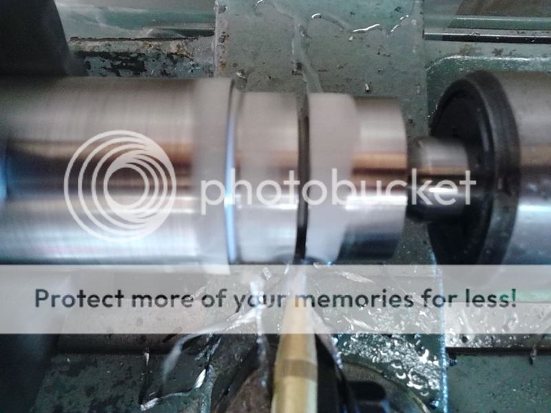
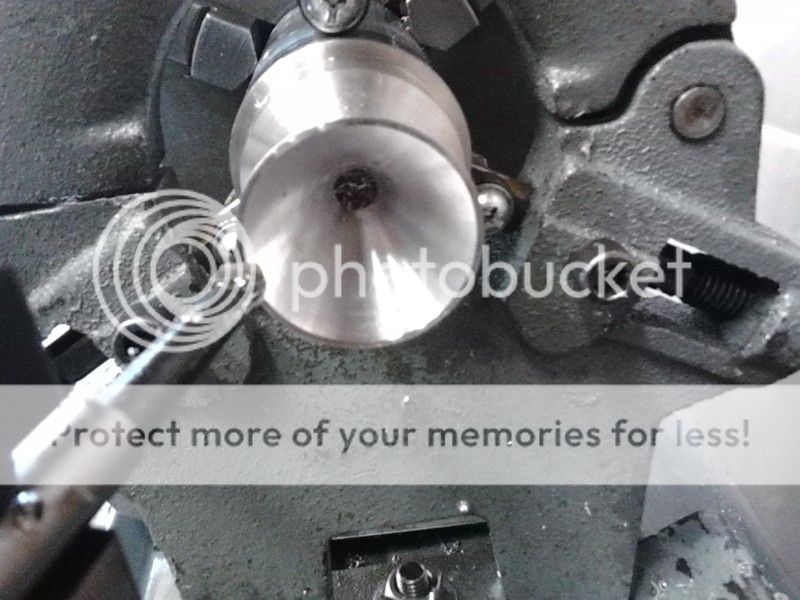
The first step in this process is to plunge cut into the round stock to make the "waist" of the K baffle. The waist needs to be radiused so I modified a parting blade for the job.


And got to cutting


I have to say, cutting aluminum again was nice. And with the new coolant system going, it really cut fast.


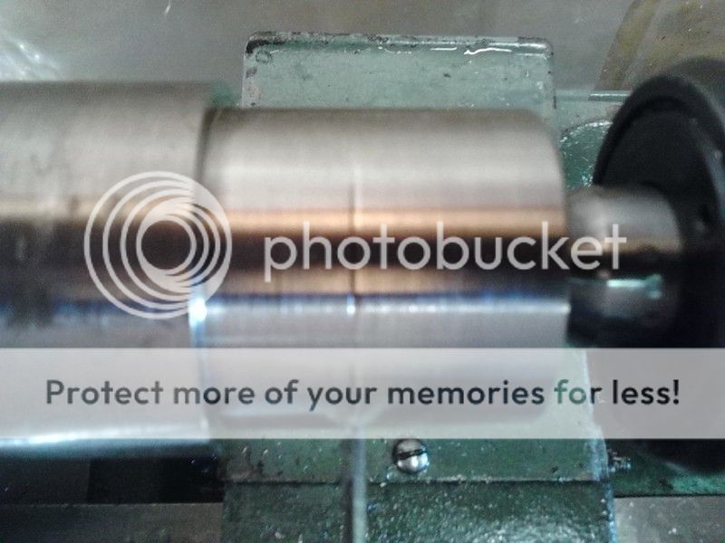
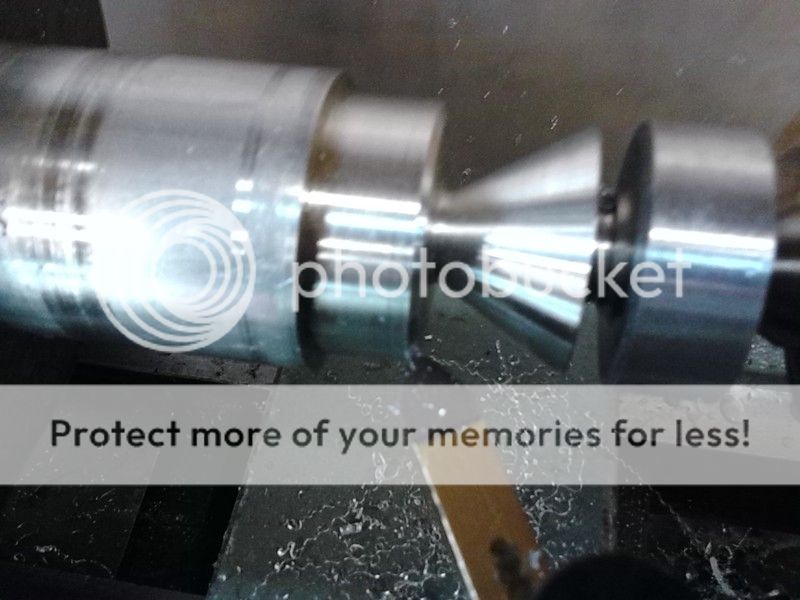
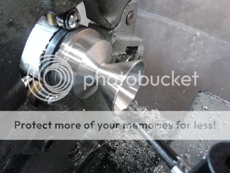
In the following picture you see I've started the 60* cut making the outside cone portion of the K. You'll also note the deep cuts to the right. That was a mistake I made. I cannot trust the dials when cutting titanium do to the flexing of the lathe. So I wanted to figure out what I needed to do in order to get some measuring tools down into the plunged cut made by the modified cut off blade. Well, I got carried away and went down too far on a second pass. Soooo, I had to move over and start again.


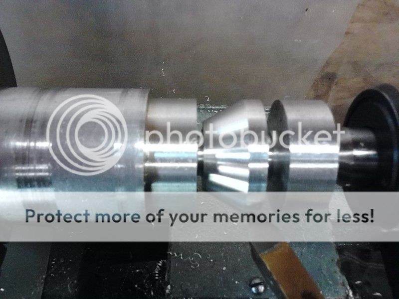
and making some chips
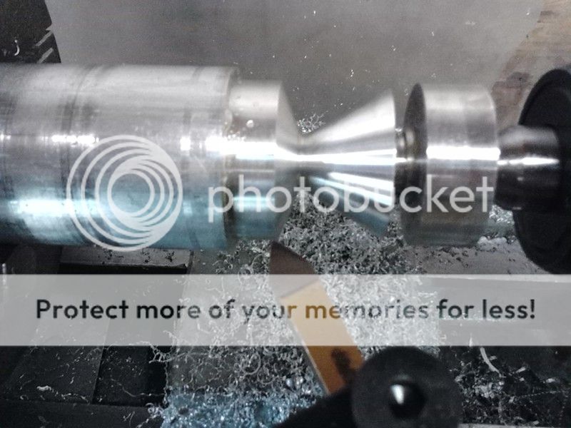


Looking good


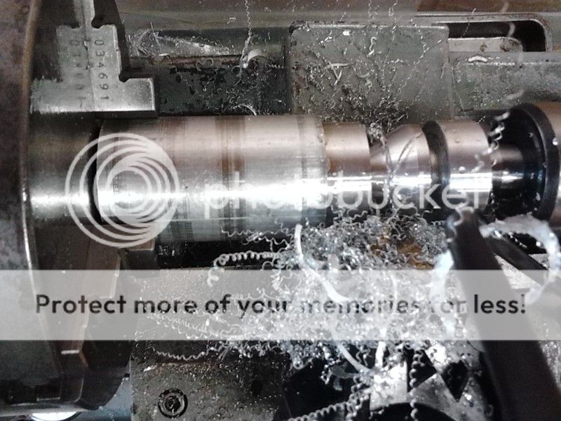
Now it's time to put the angle on the inside of the plate.


Looking good (again)


Ok, now it's time to chop off the mistake and get to work on the inside of the cone portion.


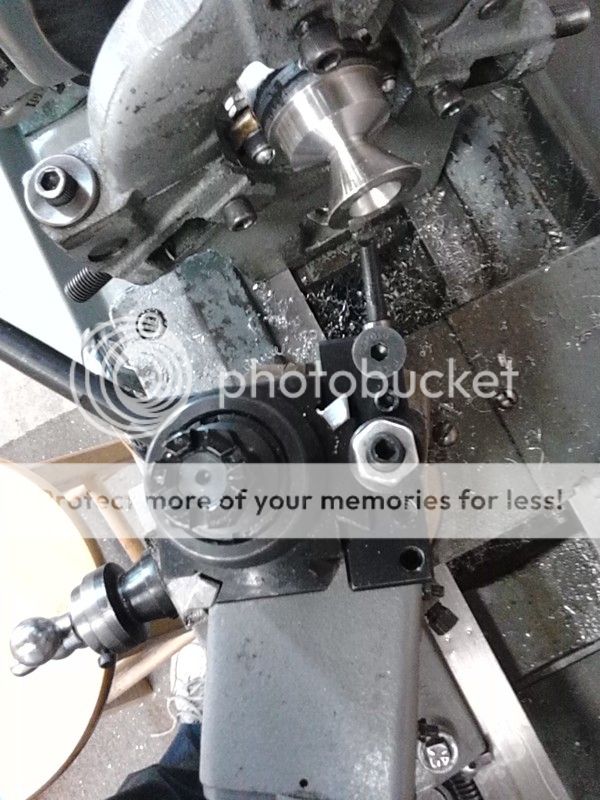
A picture of how the boring bare was set up.
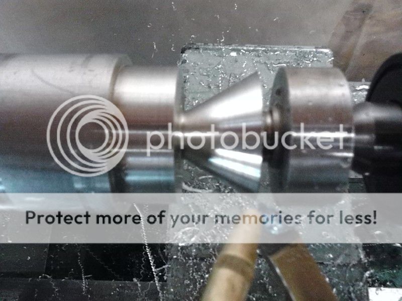
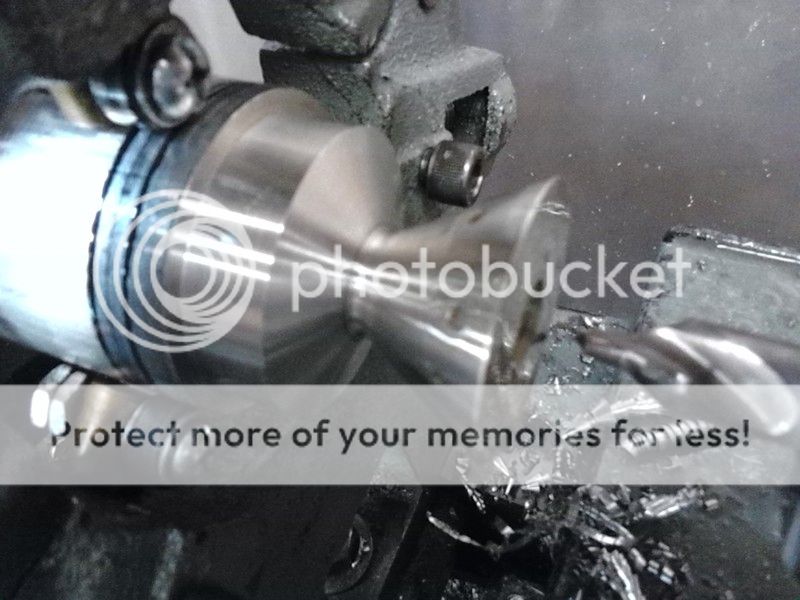


And the cone


I just wanted to interject here for a moment because this picture reminds me of sometheing Smokey Wolf was talking about.

OOPS, HIT THE WRONG BUTTON! DIDN'T MEAN TO POST THIS YET! PLEASE DON'T POST ANYTHING TILL I GET THIS FINISHED AND EDITED DOWN. THANKS!

Ok, Smokey once was talking about how nice the finish looked on one of my posts. I thought that was very nice of him to say and figured he was just being kind. See, I always keep my tool bits sharp, and make adjustments to angles of cuts to insure I'm getting a proper finish as that indicates you have everything set up right. Something I figured everyone always does. Weeeeell, I've recently been looking at youtube vides of folks doing K-baffles to help me get ideas on how to do my setups.

I was very wrong in my assumptions. There are some horrible, awful finishes being posted - and out of aluminum too! Some folks have absolutely no idea about spindle speeds and feed rates. It just floored me that someone would put on the internet some of the things I saw. I get it now Smokey. Thank you!

Ok, back on topic.


And here it is, well mostly


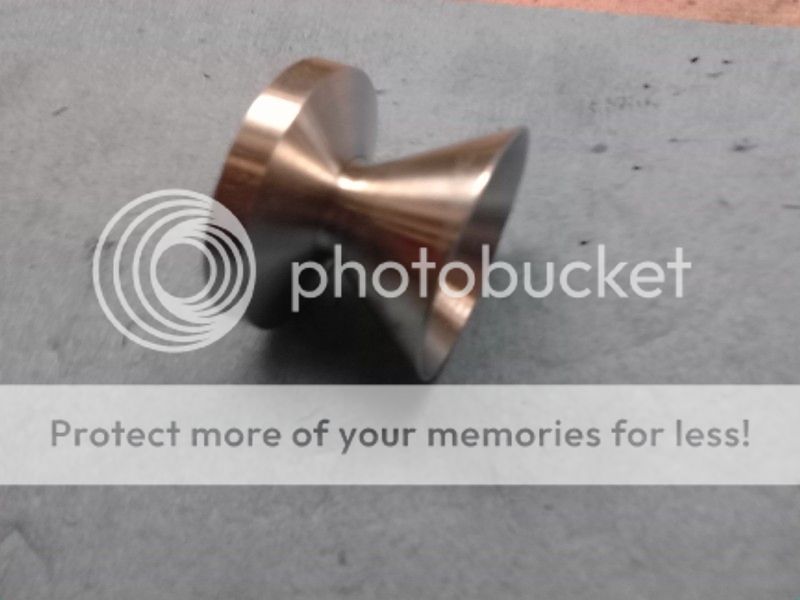
The next step will be to carve out the plate section.


But, since I'm already set up to do the above stuff, I'm going to do another in aluminum and two more in titanium. Then I'll carve out the plate.

Ok, this concludes this post. I hope to get another installment done this evening.

Thank you all for watching, commenting, and playing along.
 
Last edited:

L1A1Rocker

Active Member
I know I told ya'll I was running low on titanium for this build. Well, I was down to my last K-baffle and had just a few inches left (under 3"). I could not insert the stub into the jaws to get a good support grip. In order to have enough material sticking out I could only put about 1/2" of material into the jaws. I had to do a bit of thinking to get one more baffle out of this.


And my live center was just a bit too small to support this if I removed the steady rest


So out comes Big Betty


Nice to have a bull nose live center!


Some tight quarter to work in here.


But I'm getten er done


Taking a quick measurement off the live center LOL.


Almost there


And time to chop it off. I know I'm committing a cardinal sin here. You never NEVER part of a peace supported at both ends like this. But, I had to have this support for as long as I could keep it. I watched my dials and when I knew I was getting close I'd remove the live center. If worse came to worse, I'd remove the whole thing and use a hack saw on it.


Yep, I was very nervous here. Notice I DID move the peace back into the chuck jaws for this.


And it worked fine. Guess I was just a nervous ninny.

Check this out. Out of a 12" stick, this is my waste (aside from the bits machined off to square it up between operations)


Time to do some cleaning.


L1A1Rocker

Active Member
Looks great! Looking forward to your future post on machining the face. Thanks for taking the time to post the detailed explanation and photos!

Thank you. Next post I'll have pics of machining the plate - promise. I took a lot more pics, but some just don't make it into the write up. If you're interested, just click on a pic to take you to my photobucket account. You can paruse all the pics there - even the ones that didn't make the write-up.
 

L1A1Rocker

Active Member
It finally came time to carve out the back and I had to make a decision that I had been putting off. What design to go with on the face of the plate? There are numerous basic designs, and even more variations on those designs to consider. I think the term is analysis paralysis. Anyhow, after talking with some folks "in the industry" that I respect, I finally decided on a "notch" design like so.

IMG_20151026_163201.jpg


So it was time to get to work

Step one was to "uniform" the face.


Drill out the bore


And start carving out the inards. Actually I need to make a bit of a "shelf" that the skirt of the preceding K-baffle will interface with. This adds strength to the skirt and keeps the carbon from contacting the inside of the tube. This is important if you plan to take this thing apart anytime in the future. Some call this "nesting the Ks".


A re-profiled cut off blade came in handy to dig in like I did on the rear endcap.


I used the same re-profiled cut off blade to do the notch angle.


Just about done


I also angled the other side.


Well, that's one . . .


FYI: the two in front are aluminum, the two in back are the titanium ones.

Next up, the tube.


No, really it's not that long LOL. I trued the end up and chopped a hunk of it off. Then it was time to start threading that titanium tube.


A little about the tube. I did a bit of talking with folks and the thinnest I could go for a screw together can was .054 Grade 9 titanium. That meant some pretty fine threads - 32 tpi.


Okey-dokey. After using my three hands to hold all the peaces together with the tube beside them, I decided exactly how long the tube should be. It was time to flip the tube and cut it to exact length.


I think I'm close to my picture limit per post so I'll stop there. But I will continue - soon.
 

minmax

Active Member
Thanks for sharing your Photo Bucket account. Oh, and thank you for spending the time to edit and caption your progress.
Is that a powered hack saw? I've never seen one before.
 

minmax

Active Member
I had a question while looking at your photos. That I forgot till now. How did you determine the angle, location. Of the Dater/mouse hole? Is is just arbitrary?
 

L1A1Rocker

Active Member
Thanks for sharing your Photo Bucket account. Oh, and thank you for spending the time to edit and caption your progress.
Is that a powered hack saw? I've never seen one before.

No problem. Thanks for commenting. Shhhhh, you're reading ahead LOL. Yes, it's an old Sawmaster Automatic Hack Saw. Very handy, but I don't think OSHA would approve of it today.

I had a question while looking at your photos. That I forgot till now. How did you determine the angle, location. Of the Dater/mouse hole? Is is just arbitrary?

Reading ahead again??? LOL. I'll go into that in a post to come.

Thanks again.
 

L1A1Rocker

Active Member
Next was to cut the hole(s) in the K-baffles for the crossjet flow. Now there is just as much diversity of opinion on these hole(s) as there is for the trench design on the plate. The old way that was popular at one point, was to dish out the plate in a semicircle leaving a straight wall along the I.D./bore of the Baffle. Then, leaving the baffle in the jaws of the lathe chuck, the chuck was removed and taken over to a drill press or mill. The chuck was secured to a 45* mechinest wedge and a single hole was drilled/milled from the top of the wall on the I.D. of the plate, across the bore, and through the waist of the other side of the baffle.

Kinda like this:

It's not done this may much anymore.

Most now do some version of this:


I did it different on the advice of someone "in the industry". This was on the condition that I keep the specific angle to myself. It was a single hole milled from the base of the trench of the plate. It did not go all the way through the waist, it just started to poke through a bit.

But I had a big problem. I have a little horizontal mill with a small table. If I had a nice Bridgeport J-Head it would be a simple matter of securing the baffle to the table and turning the head to the correct angle. My solution was to make a form fitting fixture to hold the baffle in a vice mounted vertically on the milling table. With the fixture cut at the proper angle, I'd just need to secure it flat in the vice and line up my two axises and make a hole. Simple right? Yeah - but time consuming. . .

First to hack off a 2" section of 2x2 aluminum bar stock.


And then to wack off a couple of corners:


Then it was time to find my center point and center it up in a four jaw chuck.


First I did a center hole that was just a tad bigger than the waist of the K-baffle. Then I had to do a bit of a recess because the block is just a tad deeper than the K is long.


Then it was time to start a cone that would accommodate the skirt of the K-baffle.


Then I had to flip it around, line it up, and cut it out for the plate side of the baffle.

It didn't exactly fit on the four jaw though. A large hammer took care of that though.


That's better:


Check this out: (crud, still can't figure out videos)

http://vid79.photobucket.com/albums...ncer Screw on Project/VID_20151203_155618.mp4

Then I had to match the angle on the plate:


And here's the block.


And the other side of the block:


continued. . .
 

L1A1Rocker

Active Member
continuation. . .

Then it was a matter of cutting the block in half:


After a bit of sanding:


And now I bet you can see how this is going to secure the baffles in the vice:


Next post we start drilling. . .
 
F

freebullet

Guest
Ha! My father has one of those electric hacksaws, I'd never seen another. I've used it a couple times.
Your work is very nice, thank you for sharing.
 

smokeywolf

Well-Known Member
Power hacks beat the heck out of man power, but if I had the room and could find a deal on one, a horizontal bandsaw is hard to beat for efficiency. I had a pretty good sized Wilton and a wonderful garage sized (7" I think) Greenlee in the Sony Pictures Studio Machine Shop. Although the Wilton was double the size, surprisingly, the Greenlee was better built.

L1A1Rocker, glad you understand now that I was not giving meaningless compliments or unearned props, your machined finishes are as good as most "class A" machinists.
 

L1A1Rocker

Active Member
Back from Christmas holiday from North Texas. Now back to business.

The block I made to hold the K baffles is done but I needed something with a square end to help line up exactly where the hole would be. It's nothing fancy, just a peace of 3/8 round stock tuned down to the same diameter as the end (ball) mill.


And just for grins here's my little horizontal milling machine:


Now it was just a matter of putting the K-baffles in the blocks, in the vice, and do some drilling. I started on the aluminum first to get a feel for it. I prolly went overboard on the pics here. It was just kinda cool doing that angled cross drilling.


And a picture from the back side. After this the hole drilling is blind and by the dials. Fortunately the calculations, and dials were dead on - or withing a few thousandths LOL.


Here's a neat video I took drilling from the back side.

http://s79.photobucket.com/user/L1A1Rocker/media/Silencer Screw on Project/VID_20151205_142429.mp4.html?sort=3&o=16

And the result.


Something kinda funny looking. The drilling left a bit of a divot in the holding blocks.


Well, then I did the other aluminum baffle and moved on to the titanium baffles. The titanium went just fine just slow. I had set the RPM at the slowest possible setting at just 62rpm. I started the drilling and kinda started to push things a bit trying to get a feel for the titanium when the mill started bucking a bit. I backed off quickly and made a mental note to be careful, I only have the one end mill. Turned out that was more than a little bit prophetic.

Things progressed very slowly turning the handle just a couple thou at a time. After getting to the point where I was drilling blind and by the dial only . . . Oh wait a sec. Remember how I could not really do any cutting on the lathe by the dials because of the flexing on the compound? Well, that didn't happen on the mill. The dials were dead on accurate with no flexing problem. Ok, so I was drilling/milling the titanium baffle and reached the point where it was a blind operation. At this point I squirt the oil from the back side, and just as I gave a squirt with the oil can BANG!!! Quickly hit the power switch and pray that I didn't do what I think I just did. . . .

Yep, I did it. With the downward pressure of my thumb on the oil can, I carried the whole can into the work and the tip of the oil nozzle got hit by the end mill. "No big deal really, the nozzle is aluminum after all, it can't do any damage to the end mill." "Right?" I was trying to convince myself of this, but only half heatedly. The reality was that the nozzle collision had taken out a large chunk of the nose of one of the two cutting edges of the end mill.


Well I had read sense beginning this project that you really should use four flute endmills with titanium so I could at least fix that with this minor set back. WOW! Are four flute ball mills expensive in 11/32 size. Seventy five freaking dollars!!!! Ok, I ordered two more two flute ball mills at 12 dollars each. LOL

A week later I was back at it. I was able to approximate the position of the end mill but it was only an approximation. I was much closer by estimating the point at which the endmill entered the blind hole portion of the drilling. But my real saving grace on getting the depth correct was that I had done something on a lark. I had painted that "divot" on the holding blocks with blue dykem. And with a mirror and a flashlight I was able to see down that hole to the point where the dykem was being cut off. Yeah!!!

And here they are:


That concludes the cross drilling. Next up, I do something that I had kinda abandoned but not given up hope on to the front endcap and put the k-baffles on a diet.

Thanks for watching.
 
Last edited: